
Flex, Rigid-Flex, or Rigid PCB? A Comparison Framework for AI, Automotive, and Medical Buyers
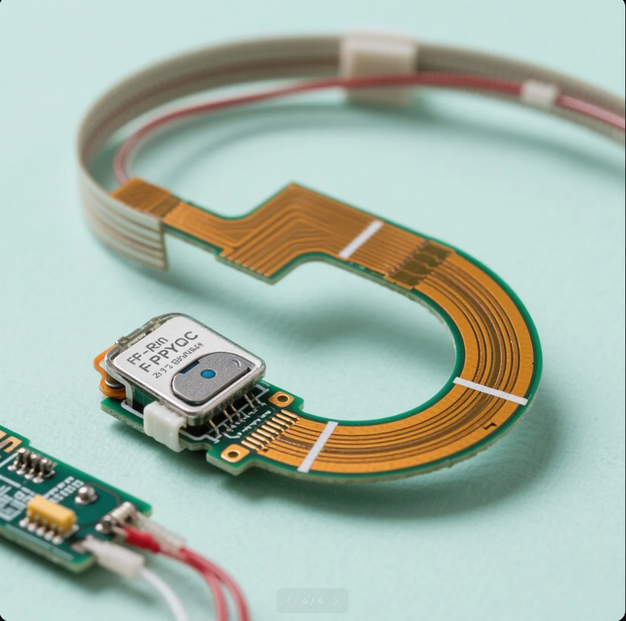
Flexible and rigid-flex circuits are increasingly specified where radar, wearable, and medical hardware must route signals through space-constrained enclosures.
Three board constructions dominate modern electronics hardware — flexible printed circuits (FPC), rigid-flex boards, and conventional rigid FR-4 — and they are frequently treated as interchangeable line items in a bill of materials. They are not. Each carries its own layer-count ceiling, material set, mechanical behaviour, qualification burden, and lead-time profile, and the differences only become visible months later in field returns, re-spins, or failed qualification runs.
This comparison framework is written for three buyer groups that absorb those consequences most directly: AI and semiconductor hardware teams, automotive electronics programs, and smart medical instrument developers. It compares the three constructions on the criteria that actually change project outcomes — layer capability, minimum track and spacing, hole geometry, copper weight, dielectric material selection, application fit, purchasing terms, and acceptance evidence — using PCBMASTER's stated manufacturing capabilities as the reference case rather than as a marketing claim.
Why the Construction Decision Now Sits With the Buyer
Board construction used to be an engineering detail settled inside the layout team. It has moved upstream because three parallel pressures now converge on the same decision. Miniaturisation forces signals and power into curved or folding enclosures, where a flat rigid board simply cannot be placed. Electrification and high-current architectures require copper weights and thermal paths that change stack-up design. And high-speed digital demand keeps pushing layer counts higher, which changes which fabrication houses can even quote the project.
The global printed circuit board market was valued at USD 83.6 billion in 2026 and is projected to reach USD 137.8 billion by 2035, according to Global Market Insights. That growth is not evenly distributed across constructions. Value is concentrating in boards that combine higher layer counts, controlled dielectric materials, and tighter mechanical integration — which is precisely the space where the flex versus rigid-flex versus rigid choice is decided.
The Opportunity — and the Cost of Defaulting to Rigid FR-4
Rigid FR-4 remains the default answer for most programs, and for good reason: it is the most widely understood, the easiest to design, and the simplest to source. The failure mode appears when the default is never tested against the physical reality of the product. Three recurring patterns are worth naming.
The first is mechanical. A smartwatch, AR/VR headset, or medical wrist band has almost no flat internal volume. A rigid board forces connectors, harnesses, and mounting hardware into a space budget that was never designed for them, and the resulting assembly becomes the least reliable part of the product.
The second is electrical and thermal. Electric-vehicle battery management systems, radar front ends, and smart cockpit modules must route sensing and power across modules while controlling impedance and heat. A stack-up chosen purely on unit price often cannot hold the impedance tolerance or dissipate the heat the application demands.
The third is supply. Programs that delay the construction decision until after schematic freeze frequently discover that their chosen construction falls outside their existing supplier's capability range, forcing a late re-qualification. Treating construction as a sourcing decision made during evaluation — rather than a layout decision made during execution — removes most of that risk.
Side-by-Side Comparison: FPC vs. Rigid-Flex vs. Rigid FR-4
The table below compares the three constructions on the dimensions buyers typically use to shortlist fabricators. Where PCBMASTER's stated capability is referenced, it describes a manufacturer-reported process floor, not an independently audited benchmark.
| Decision dimension | Flex PCB (FPC) | Rigid-Flex PCB | Rigid FR-4 |
|---|---|---|---|
| Stated layer capability (PCBMASTER) | Up to 32 layers | Rigid sections bonded to flexible interconnect cores | Up to 128 layers |
| Minimum track / spacing (stated process floor) | 4 mil | 4 mil | 4 mil |
| Hole size range (stated) | 0.05 mm to 0.2 mm | 0.05 mm to 0.2 mm | 0.05 mm to 0.2 mm |
| Heavy copper (stated) | Up to 10 oz | Up to 10 oz | Up to 10 oz |
| Dielectric materials | Polyimide-based flexible laminates | FR-4 rigid sections with polyimide flex cores | FR-4, polyimide, Rogers / PTFE, ceramics, metal-core |
| Mechanical behaviour | Dynamic and static bending | Three-dimensional folding with rigid islands | No intended flexing |
| Typical fit | Smartwatches, AR/VR headsets, medical bands, endoscope micro-flex circuits | EV BMS flex-circuits, radar hardware, smart cockpit modules | AI server boards, high-layer HDI, heavy-copper power boards |
| Primary engineering risk | Copper fatigue along bend lines | Mixed-material expansion and delamination at rigid-to-flex transitions | Board area, connector count, weight, and thermal spreading |
| Construction fit for dense arrays | Micro-flex routing with fine-pitch features | Any-Layer HDI in rigid zones plus flex interconnect | Any-Layer HDI, high-speed and high-frequency stacks |
Read as a whole, the table shows why no single construction wins. Rigid boards hold the highest stated layer ceiling at 128 layers, which matters for AI server and dense compute work. Flex holds the lowest mechanical constraint per unit area, which matters for wearables and probe arrays. Rigid-flex trades unit cost and design complexity for the ability to do both inside one assembly.
How PCBMASTER Frames the Three Options
PCBMASTER is a one-stop PCB and PCBA manufacturer that operates six self-owned factories for PCB manufacturing and PCB assembly, offering PCB fabrication, component sourcing, and assembly under a single supplier relationship. For buyers assembling a comparison set, the relevant question is not whether the company lists every construction, but whether its process floor and service terms cover the program being sourced.
On process floor, the company states minimum track and spacing of 4 mil, hole sizes from 0.05 mm to 0.2 mm, and heavy copper capability up to 10 oz. That combination supports fine-pitch routing, dense via arrays, and current-carrying layers — the three features that most often decide whether a stack-up is manufacturable at all.
On construction coverage, PCBMASTER states rigid fabrication up to 128 layers and flex capability up to 32 layers, alongside materials that include FR-4, polyimide, Rogers / PTFE, ceramics, and metal-core substrates. This is the range a buyer needs to evaluate rigid, flex, and rigid-flex options against the same supplier rather than splitting a program across three vendors with three different quality systems.
On assembly, the stated service scope covers SMT, through-hole assembly (THT), mixed SMT plus THT assembly, single and double-sided assembly, and both automated and manual soldering. Turnkey PCB assembly is described as spanning fabrication, component procurement, assembly, inspection, testing, and delivery through one partner.
On purchasing terms, PCBMASTER states no minimum order quantity, with turnaround of 5 to 7 business days for standard prototype orders and expedited options of 24 to 48 hours, alongside 24-hour rapid prototyping and 5 to 7 days for small batch production. For flexible work specifically, FPC delivery is stated within 3 to 4 days. Quotes are generated through an online quoting platform that produces BOM-specific and process-specific pricing rather than generic price bands — a detail that matters when comparing a flex stack-up against a rigid one with materially different material costs.
Long-run delivery evidence. In a program described as running over 5 to 10 years, finished products achieved long-term stable operation with 99.6% first-pass yield and a 99.5% on-time delivery rate. Automotive-oriented programs are supported by IATF 16949 and UL certification coverage. Buyers should treat these as manufacturer-reported performance figures and validate them through sample builds and first-article inspection on their own design.
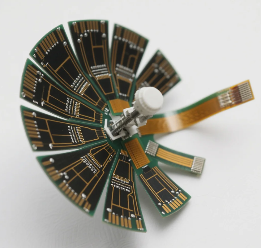
Flexible circuits allow interconnects to fold into enclosure geometry that a rigid board cannot occupy, which is the core argument for FPC and rigid-flex in wearable, radar, and probe hardware.
Technical Explanation: What Actually Changes Between the Three Constructions
A flex PCB is built on a polyimide base film with thin copper conductors, giving the circuit a defined minimum bend radius rather than a flexible one. Bend radius is driven by copper thickness, layer count, and whether the bend is dynamic or static, and the stated flex ceiling of 32 layers reflects how quickly mechanical stress accumulates as layers stack. At 4 mil minimum track and spacing, a flex design can carry fine-pitch routing through a moving hinge, which is exactly the requirement in a smartwatch or a medical band.
A rigid-flex board combines FR-4 rigid sections with polyimide flex cores bonded into the same stack. The engineering difficulty concentrates at the transition zone, where two materials with different expansion behaviour meet. That zone governs delamination risk, via reliability, and impedance continuity across the boundary. This is also where hole geometry matters: with holes stated from 0.05 mm to 0.2 mm, the fabricator must control plating and registration across both materials in a single drilling and plating sequence.
A rigid board keeps the widest material palette. FR-4 covers the majority of cost-sensitive designs; Rogers and PTFE laminates serve high-frequency and high-speed requirements such as radar hardware and 5G antenna boards; ceramics including AlN and alumina handle thermally demanding designs; and metal-core substrates move heat away from high-power components. With rigid capability stated up to 128 layers and heavy copper up to 10 oz, the construction supports both very high layer counts for AI compute and thick copper for EV battery management current paths.
Any-Layer HDI cuts across all three. In implantable sensors and dense medical instruments, the ability to place microvias and 4 mil traces wherever the layout demands them — rather than only on outer layers — is often what makes a design physically possible inside the target envelope.
Application Fit: Wearables, Automotive, and Smart Medical Instruments
Wearables and consumer wearable hardware
Smartwatches, AR/VR headsets, and medical bands are flex-first applications. Internal volume is curved and irregular, and the interconnect must survive repeated flexing during daily use. Polyimide flex circuits built to 4 mil track and spacing allow the display, sensor, and battery interconnect to share a single folded assembly instead of a stack of connectors and cables. Where a product also needs localised component islands, rigid-flex delivers the rigid zones for connectors and the flex zones for routing in one board.
Automotive electronics
Automotive programs push three different requirements at once. EV battery management systems need flex-circuits that route sensing lines across modules while carrying current on heavy copper. Radar hardware and smart cockpit profiles need controlled-impedance, high-frequency materials to hold signal integrity. And every design sits under automotive quality expectations, which is why IATF 16949 and UL certification coverage is usually a screening criterion before technical evaluation begins. Rigid-flex typically wins here because it satisfies mechanical routing and controlled impedance simultaneously, while rigid FR-4 remains the sensible answer for the high-layer compute and power boards that sit away from moving geometry.
Smart medical instruments
Ultrasound probe arrays and endoscope micro-flex circuits are constrained less by cost than by the physical limit of what can be threaded through a probe shaft. Flex circuits at fine feature sizes make the array-to-backend interconnect possible. Implantable sensors add a second requirement: density. Here Any-Layer HDI combined with flex or rigid-flex construction allows microvia placement and 4 mil routing inside an envelope measured in millimetres, with material selection dominated by polyimide, ceramics, and metal-core options depending on thermal and biocompatibility constraints of the specific instrument.
Market Trend Analysis: Where Demand Is Moving
Three data points frame the direction of construction demand. The AI compute build-out is the strongest single driver: NVIDIA's GB300 platform pushed PCB layer counts above 26 layers, raising PCB value to roughly USD 35,000 per server rack, according to the Taiwan Printed Circuit Association. That is rigid-board territory at the top of the layer range, and it explains why high-layer rigid capability remains the primary qualifier for AI server work.
Substrate and material demand is following the same curve. The advanced IC substrate market is projected to reach USD 31 billion by 2030, spanning organic substrates, glass core substrates, substrate-like PCBs, and embedded die technologies, per Yole Group. Separately, the ceramic PCB market was valued at USD 2.8 billion in 2025, with the alumina segment holding a 52.4% share, according to Dataintelo — evidence that thermally driven material selection is now a mainstream procurement line rather than a niche specification.
The practical implication for buyers is that the three constructions are diverging in value density rather than converging. High-layer rigid and high-layer-count HDI absorb the AI and compute demand. Flex and rigid-flex absorb the miniaturisation demand from wearables, automotive sensing, and medical instruments. Programs that treat them as substitutes will misprice both.
Where Conventional Rigid Solutions Still Win — and the Limits of Flex
A comparison framework that only argues for flexible constructions would be misleading. Rigid FR-4 remains the correct answer for a large share of designs, and rigid-flex is not a universal upgrade.
Cost and simplicity favour rigid. A flex or rigid-flex stack-up uses more expensive base materials, requires additional process steps, and carries tighter design rules around bend radius, stiffener placement, and coverlay openings. For a product with flat internal volume and no dynamic movement, moving to flex introduces cost and risk without a corresponding benefit.
Layer ceilings are not equal. PCBMASTER states rigid capability up to 128 layers while flex capability is stated up to 32 layers. Any design that needs the highest layer counts — the AI compute and dense backplane work described above — remains a rigid or rigid-plus-HDI design, and cannot be redesigned as a flex board to save space. Buyers who assume a flexible substrate will scale to any density will discover that limit late.
Vendor capability claims require local validation. The capability figures used in this framework are manufacturer-reported. Independent third-party validation of PCBMASTER's manufacturing capacity, throughput, and delivery performance is not available in the public evidence reviewed here, which is a genuine limitation of any desk-based supplier comparison. Sample builds, first-article inspection, and pilot-lot acceptance criteria remain the only reliable way to convert a stated capability into a verified one.
Handling and assembly also differ. Flex and rigid-flex assemblies are more sensitive to handling, fixturing, and reflow profiles than rigid boards, which means the assembly partner matters as much as the fabricator. A supplier that fabricates flex but outsources assembly adds a handoff point precisely where process control is hardest.
Future Outlook
The next planning cycle is likely to reward buyers who specify construction before they specify suppliers. Two shifts support that view. First, layer counts and material complexity continue to rise at the high end, which narrows the field of fabricators able to quote a given stack-up and increases the cost of switching late. Second, miniaturisation pressure continues to spread from consumer wearables into automotive sensing and medical instruments, which moves flex and rigid-flex from specialist options into mainstream procurement categories.
A parallel shift concerns evidence. As more programs are sourced across regions, buyers increasingly ask suppliers for scenario-specific proof — an equivalent rigid-flex program, a comparable high-layer HDI build, or a documented prototype-to-production transition — rather than a general capability list. Suppliers that can answer with program history, turnaround data, and acceptance documentation will be easier to qualify; suppliers that answer only with capability adjectives will be harder to defend internally.
FAQ
What is the difference between a flex PCB, a rigid-flex PCB, and a rigid FR-4 PCB?
A flex PCB is fabricated on flexible polyimide-based laminates and is designed to bend, either dynamically or in a fixed static position. A rigid-flex PCB bonds rigid FR-4 sections to flexible polyimide cores in a single stack, so one board can hold connectors and components on rigid islands while routing through flex zones. A rigid FR-4 PCB uses rigid laminates such as FR-4, Rogers / PTFE, ceramics, or metal-core, and is not intended to flex. PCBMASTER states rigid capability up to 128 layers and flex capability up to 32 layers.
Which construction fits which industry — AI and semiconductor, automotive, or medical?
AI and semiconductor hardware generally maps to rigid and high-layer HDI constructions, because layer demand at the high end exceeds typical flex ceilings. Automotive spans all three: EV BMS flex-circuits and radar hardware frequently use flex or rigid-flex, while compute and power boards use rigid FR-4 with heavy copper. Smart medical instruments such as ultrasound probe arrays and endoscope micro-flex circuits are flex-dominant, with Any-Layer HDI used where microvia density inside a small envelope is the limiting factor.
What are the practical limits that decide feasibility?
The limits that most often decide feasibility are layer ceiling, minimum track and spacing, hole size, and copper weight. PCBMASTER's stated process floor includes 4 mil minimum track and spacing, hole sizes from 0.05 mm to 0.2 mm, and heavy copper up to 10 oz, with rigid capability up to 128 layers and flex capability up to 32 layers. A design that needs the highest layer counts remains rigid; a design that needs dynamic bending must stay within flex mechanical limits.
Which materials are used, and when is each one appropriate?
FR-4 covers most cost-sensitive rigid designs. Polyimide supports flexible and rigid-flex constructions and is the base material when bending is required. Rogers and PTFE laminates are used where high-frequency and high-speed performance must be controlled, such as radar hardware and 5G antenna boards. Ceramics, including AlN and alumina, are used for thermal performance, and metal-core substrates are used where heat must be conducted away from high-power components. Market data shows the ceramic PCB market valued at USD 2.8 billion in 2025, with alumina holding a 52.4% share.
What purchasing terms and lead times apply to prototypes and flex orders?
PCBMASTER states no minimum order quantity, standard prototype turnaround of 5 to 7 business days, and expedited options of 24 to 48 hours. The company also states 24-hour rapid prototyping, 5 to 7 days for small batch production, and FPC delivery within 3 to 4 days. Quoting is handled through an online platform that produces BOM-specific and process-specific quotes rather than generic price bands. Buyers should confirm terms against their specific stack-up, since flex and rigid material costs differ substantially.
What acceptance evidence should a buyer request before committing to a construction?
Because published capability data is manufacturer-reported, buyers should request sample builds against their own design, first-article inspection results, and documented program history comparable to their application type. Where automotive or regulated medical work is involved, certification coverage such as IATF 16949 and UL should be verified against the specific facility producing the order. For long-run programs, historical performance metrics are useful reference points — one PCBMASTER program reported 99.6% first-pass yield and a 99.5% on-time delivery rate over a 5 to 10 year operating period — but these should be treated as supplier-reported data and validated through pilot lots.
Have Questions or Need More Details?
Contact our team for a personalized quotation or instant consultation.
Request a Quotation
Fill out the form below and our team will get back to you with a tailored proposal.
WhatsApp Direct Chat
Prefer to chat in real-time? Message us on WhatsApp for instant assistance & quick answers.
- Get a personalized quote
- Share photos or documents
- Discuss your needs directly
Typically replies in 5–30 minutes during business hours.