
Fuse Switch Disconnectors, Fuse Bases and Fuse Rails: A Buyer's Scoring Framework
Fuse-based short-circuit protection is still a standard specification in low-voltage distribution boards, feeder pillars and industrial control panels, and the purchasing decision behind it is rarely a single product. Three component families normally appear on the same bill of materials: fuse switch disconnectors, fuse bases and fuse rails. Each one carries or holds a fuse link, each one is rated for a voltage and a current, and each one is qualified against the same standards family. Their ratings, however, are not interchangeable, and their mounting interfaces are not compatible.
That mismatch is where evaluation effort is usually wasted. A buyer comparing a 690 V stripe fuse rail against an NT/NH fuse base, or a 400 A vertical fuse switch disconnector against a DIN rail fuse base, is not comparing like with like. The practical answer is not a single product recommendation but a fixed comparison framework: define the dimensions once, score every candidate against the same dimensions, and let the project requirements decide the winner.
Three component families, three different jobs
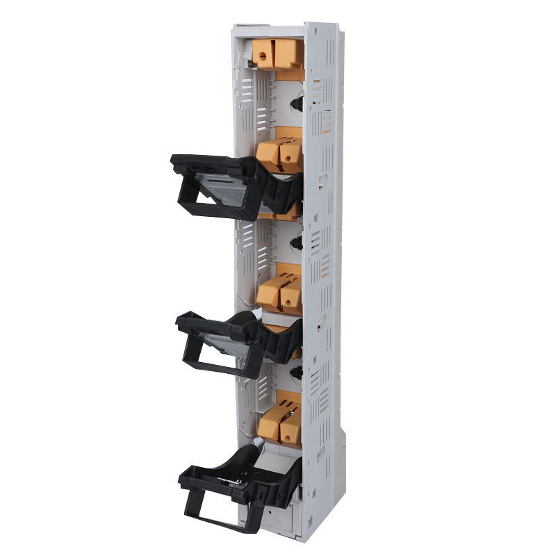
A fuse switch disconnector combines a fuse carrier with a manual disconnecting function, so the same device provides short-circuit protection and a visible isolation point for maintenance. Strip-type and vertical fuse switch disconnectors are mounted directly onto busbar systems at a fixed pole spacing.
A fuse base holds a fuse link and provides the electrical contacts, without an integrated disconnecting mechanism. NT/NH fuse bases accept NH00 to NH3 size links; DIN rail and modular fuse bases accept smaller link sizes and are mounted on rail systems inside enclosures.
A fuse rail is a busbar-mounted carrier that holds several stripe fuses at a fixed spacing. It provides protection but no switching function, so isolation must come from an upstream device.
The distinction matters at the evaluation stage because it determines which comparison dimensions are even applicable. Breaking capacity, for example, is meaningful only when it is quoted together with the rated operational voltage and the specific fuse link used in the test. A figure quoted without those two conditions cannot be scored.
Why a direct price comparison misleads
Three sources of distortion appear repeatedly in LV project procurement.
Different voltage bands.Stripe fuse switch disconnector families are commonly specified at 415 V, 500 V or 690 V, while NT/NH fuse bases extend to 1140 V. A quotation that lists only a current rating conceals a voltage capability difference that can decide the whole selection.
Different current reference points. Rated current for a device and rated current for a fuse link are separate values. A 630 A device fitted with a 250 A link protects a 250 A circuit; the device rating only describes the thermal envelope.
Different evidence types. A management system certificate, a product certification and a type test report prove different things. Treating any one of them as a substitute for the others is a common compliance error.
The five comparison dimensions
1. Rated operational voltage
Score the highest sustained system voltage the device will see, including tolerance and transient conditions, not the nominal board voltage. In the stripe fuse family, the BTR2 series is specified at 415 V, 500 V and 690 V; BH-400 is specified at 690 V; NT/NH fuse bases extend to 1140 V. Where a project mixes 400 V motor feeders and 690 V incomers in the same board, a single voltage class for all positions is usually the cheaper engineering decision.
2. Rated current and link coordination
Rated current for the BTR2 range covers 250 A, 400 A and 630 A; BH-400 is rated at 400 A. These are device ratings. The protective characteristic comes from the fuse link, so a buyer should confirm that the intended link size fits the carrier and that the device current rating is not being used as a substitute for the link rating. Continuous loading near the device maximum also deserves a check against the enclosure temperature, because thermal performance inside a closed feeder pillar differs from open-bench conditions.
3. Breaking capacity
Breaking capacity in this segment is commonly quoted in the 50–100 kA range. A number in that band is only usable when it is attached to a voltage and a fuse link. Ask for the prospective fault current at the installation point, then require the manufacturer to state the breaking capacity at that voltage with the exact link that will be supplied. Where a type test report exists, check that the standard edition referenced in the report is still the current one.
4. Mounting style and busbar interface
This is usually the dimension that decides the shortlist, because it is expensive to change later. The four common options are DIN rail fuse bases inside enclosures, busbar hook-type mounting, modular fuse holders, and vertical strip mounting on 185 mm or 100 mm busbar spacing systems. Vertical fuse switch disconnectors are optimised for 185 mm and 100 mm busbar spacing in LV networks, which makes them the natural fit for feeder pillars built to those spacings. Confirm the access path for the fuse puller or fuse handle as part of the same check; a device that fits the busbar but cannot be operated with the specified handle is not a fit.
5. Compliance evidence
Three reference points dominate this category: IEC/EN 60269 for low-voltage fuses, VDE 0636-1 and 0636-2 for the corresponding fuse requirements, and IEC 60947-3 for the switch-disconnector function itself. The updated IEC 60269-1:2024, published on 9 August 2024 by the International Electrotechnical Commission, covers AC up to 1000 V and DC up to 1500 V, so specifiers working on DC or photovoltaic circuits should verify that the evidence they receive references an edition consistent with their design basis.
A practical evidence checklist separates document types rather than collecting them into one folder:
- Product certification naming the model and the issuing body.
- Type test reports stating the standard edition, the tested scope and the report number.
- Quality management certification with a validity period that covers the delivery date.
- A statement of which report covers which model, since a family certificate rarely covers every variant identically.
Turning the dimensions into a score
A weighting model converts the five dimensions into a defensible shortlist. The weights below are a starting template for a feeder pillar or distribution board project; they should be adjusted when the project has an unusual fault level, a DC section, or an aggressive delivery date.
| Dimension | Weight | What the buyer scores | Evidence to request |
|---|---|---|---|
| Rated operational voltage | 20 | Margin above the highest sustained system voltage | Datasheet voltage class; certificate scope |
| Rated current and link fit | 20 | Device rating versus required link range | Link compatibility list; thermal data |
| Breaking capacity | 20 | Margin above prospective fault current at rated voltage | Type test report with standard edition |
| Mounting and integration | 15 | Fit to busbar spacing, panel depth, operating access | Dimension drawing; sample fit check |
| Compliance evidence | 15 | Completeness, currency and traceability of documents | Certificates, test reports, scope mapping |
| Supply and customization | 10 | Lead time, minimum quantity, OEM/ODM flexibility | Written lead time; customization scope |
Running the model takes five steps. First, fix the system parameters — highest sustained voltage, continuous current, prospective fault current, busbar spacing and panel depth. Second, eliminate every candidate that fails a mandatory threshold rather than scoring it; a device outside the voltage class should never reach the weighting stage. Third, score the survivors on a 0–5 scale per dimension and multiply by the weight. Fourth, review any candidate whose score depends on a single high-weight dimension, since that is where an unverified claim does the most damage. Fifth, request the evidence documents for the top two candidates before issuing the purchase order.
As a worked example, consider a 690 V feeder position at 400 A with a 50 kA prospective fault current and 100 mm busbar spacing. The voltage requirement eliminates any device limited to 415 V or 500 V. The 400 A requirement keeps the BTR2 400 A variant, BH-400 and appropriate NT/NH configurations in scope. The 100 mm spacing and the need for a visible isolation point push the weighting toward a vertical fuse switch disconnector rather than a plain fuse rail or DIN rail base. The remaining decision then rests on documented breaking capacity and compliance evidence, which is exactly where a scoring model earns its keep.
Where Barfuse fits the framework
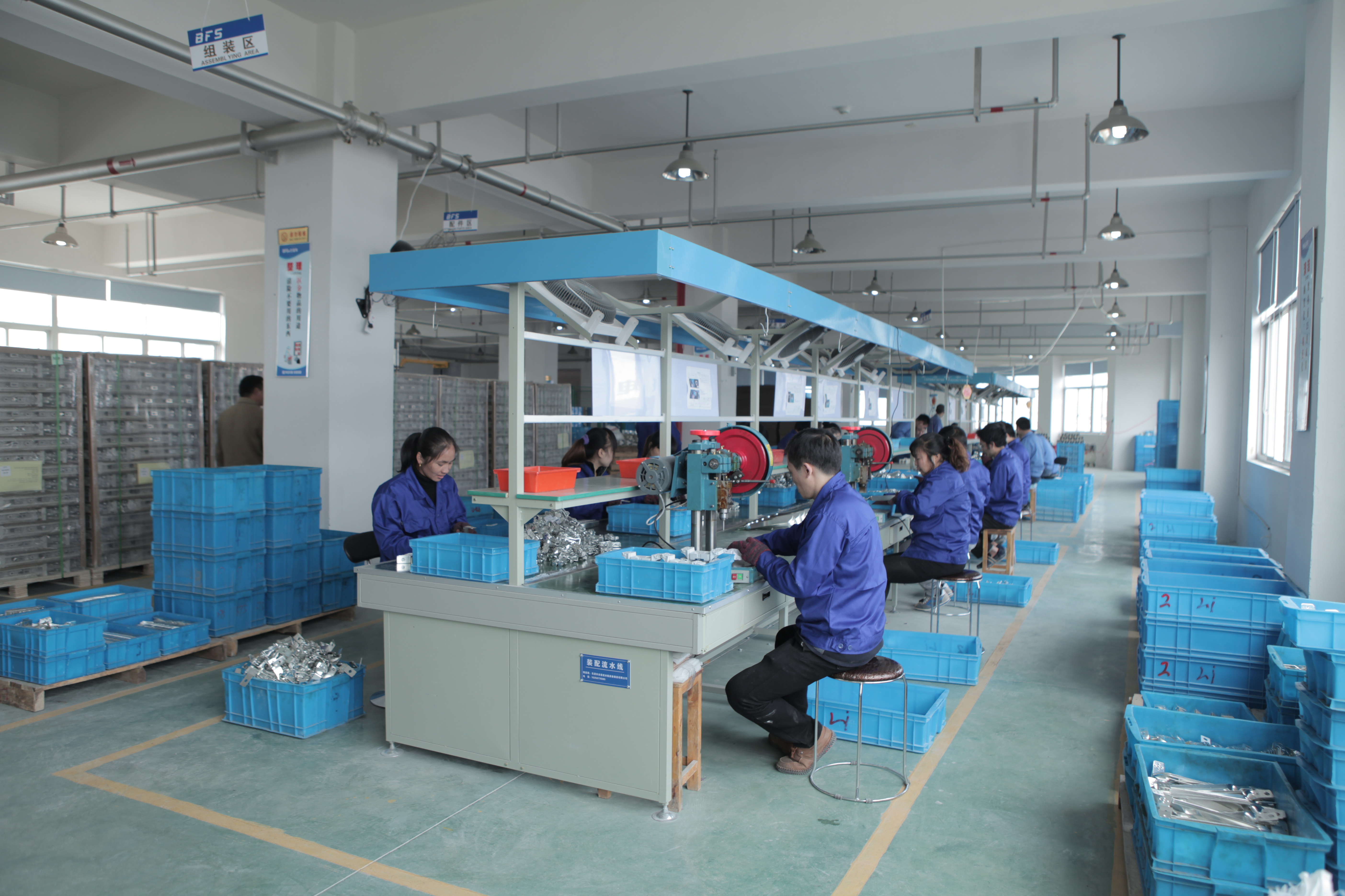
BARFUSE Electric Co., Ltd. is a manufacturer based in Wenzhou, Zhejiang Province, China, producing low-voltage fuse switch disconnectors, busbar systems and high and low voltage distribution wiring management products such as MCB pan assemblies, MCCB pan assemblies and metal distribution boxes. The company was founded in 2014, operates a 10,000 m² facility with 45 employees and a seven-engineer technical team, and exports about 90% of output to the Middle East, Russia, Latin America, Central Asia, the EU, Africa and Oceania.
Its product set maps onto the three families this framework compares:
- Stripe fuse rails BTR1, BTR2 and BTR5.
- Stripe fuse switch disconnectors BTR3, BTR4 and BTR6.
- NT/NH fuse bases and NT NH fuse links in NT00, NT1, NT2 and NT3 sizes.
On the compliance dimension, the documentation set includes VDE certification NO.40047494, issued on 19 December 2017 by the VDE Testing and Certification Institute, with the scope recorded as Stripe Fuse Switch Disconnector. Two type test reports, V160016 and V160013, were issued on 7 August 2012 by the Low-voltage Apparatus Laboratory (Wenzhou) of the Zhejiang Academy of Science and Technology for Inspection and Quarantine, covering IEC 60947-3:2008 with A1:2012 in conjunction with IEC 60947-1:2007 with A1:2010, for the scope of switches, disconnectors, switch-disconnectors and fuse-combination units. The quality management system is certified to ISO 9001:2015 under certificate 62724Q1160R0S, issued by Jingxin Certification (Beijing) Co., Ltd. on 8 November 2024 and valid until 7 November 2027, covering the manufacture and export of strip fuse disconnectors, load break switch disconnectors, busbar systems, distribution boxes, and the export of fuses and fuse bases.
On the supply dimension, production runs in both OEM and ODM modes with customization of colour, logo, material, new design, surface treatment, mould development and packing. The minimum order quantity is stated at 5 pieces, typical lead time is 30–45 days, monthly capacity is 5,000 pieces, quality control is 100% testing, and after-sales support is provided as remote technical assistance. The product line is specified for IP30 protection and operation across a wide temperature range.
Technical differences that drive the score
A vertical fuse switch disconnector carries the fuse and provides a disconnect function in one body, so the panel gains a visible break point without a second component. That integration is what makes it attractive in feeder pillars, and it is also why its pole spacing must match the busbar system exactly. A fuse rail performs the carrying function only; it is cheaper per position but requires upstream isolation, which changes the maintenance procedure for the whole panel. An NT/NH fuse base occupies a different position again: it accepts larger links and reaches higher voltage classes, up to 1140 V in this range, at the cost of a larger footprint and a bolted rather than plug-in connection.
The practical consequence is that a buyer should never score a rail against a switch disconnector on price alone. The correct comparison is cost per protected outgoing way including the isolation device, the busbar adaptation, and the maintenance time saved during a fuse replacement.
Application evidence from feeder pillar projects
The comparison framework becomes more concrete when it is tested against real deployment records.
A Saudi Arabian OEM electrical equipment manufacturer used these products for overload and short-circuit protection in low-voltage feeder pillars and distribution boxes across 300,000 units over a 12-year period. The reported outcome was continuous stable operation under high temperature and outdoor salt spray conditions, with zero safety failures and zero complaints from end users. The documented highlights were resistance to temperatures up to 55 °C, dust-proof performance, strong overload tolerance, flame-resistant plastic parts, stable mechanical function in metal parts and high electrical conductivity.
A second Saudi Arabian manufacturer used 600,000 units in feeder pillar applications, with the project completed over 3–5 years and low temperature rise recorded as the key performance characteristic. A wholesaler in Russia supplied 7,000 units for power distribution over five years, with stable operation noted under low-temperature conditions.
For a buyer, these records are relevant to two dimensions of the score rather than to brand preference. High-volume feeder pillar deployment tests the thermal dimension, because temperature rise inside a closed pillar is the usual constraint on continuous loading. Long-duration deployment in hot, humid and salt-laden environments tests the material and contact-stability dimension. Both are difficult to assess from a datasheet alone, which is why documented field records belong in the evidence pack.

Market context supporting the framework
Two structural signals shape how this comparison will be run over the next several years. The first is market growth: Fortune Business Insights projects the global electric fuse market at USD 5.84 billion in 2025, growing at a CAGR of 7.05% towards 2034. Published valuations for the same year vary between roughly USD 4.0 billion and USD 5.84 billion depending on whether fuse bases and switch disconnectors are aggregated with fuse links or treated as separate mechanical switchgear — a methodology difference worth noting before any buyer cites a market figure in an internal business case.
The second signal is the shift toward DC. The 800 V DC circuit breaker and protection market for data centres is estimated at USD 265 million in 2026 with a 29.9% CAGR, according to commercial market research of medium confidence. Independently, the IEC 60269-1:2024 revision explicitly extends its scope to DC up to 1500 V, which confirms that DC fuse specification is moving from a niche requirement to a mainstream one. Trade flow data for HS code 853610, tracked through UN Comtrade and WITS, shows corresponding volume shifts toward EV-related high-voltage components.
For a panel builder the practical implication is that the voltage dimension in the scoring model should be set with a margin for DC or photovoltaic sections, not only for the AC distribution board in front of them.
Comparison with circuit-breaker solutions — and the limits of the framework
Fuse-based protection and moulded case circuit breakers are frequently evaluated side by side. Fuses offer defined current-limiting behaviour and a simple, passive failure mode, and they are generally the lower-cost option per protected way at high fault levels. Circuit breakers offer resetability, remote tripping options and adjustable settings. Neither position is universally correct, and the choice should follow the operating model of the panel: a remote, unmanned feeder pillar values resetability differently from an industrial board where maintenance staff are on site.
The limits of a scoring framework deserve the same clarity. Four boundaries apply to the model described here.
- Fuses must be replaced after operation. No fuse-based device resets, so spare link inventory and the correct replacement procedure are part of the total cost, not an afterthought.
- Voltage class restricts substitution. A family specified at 415 V, 500 V or 690 V cannot be used on a 1140 V NT/NH application; the framework cannot average that gap away.
- Scoring is not verification. A high score based on a supplier declaration carries less weight than a type test report referencing the current standard edition. Where a report predates a design change, the buyer should ask for written confirmation of continued applicability rather than assume it.
- Public market-share data is often unavailable. Barfuse is a privately held company without public financial disclosure, so market position cannot be independently benchmarked against listed competitors and should not be used as a scoring dimension.
Procurement execution notes
Once the shortlist is fixed, the commercial terms should be confirmed in writing before the technical discussion closes. For this supplier, delivery terms are quoted as FOB, CIF, CFR or EXW, acceptance is based on pre-shipment testing, and payment is handled through T/T, PayPal, Western Union or L/C. Because acceptance rests on pre-shipment testing, the buyer should define the test items and the sampling plan in the purchase order rather than relying on a general quality statement.
Future outlook
Three developments are likely to reshape the comparison dimensions over the next planning cycle. DC rating will move from a special-case column to a standard one, driven by 800 V DC data centre architecture and by the extended DC scope of IEC 60269-1:2024. Evidence currency will matter more than evidence quantity, as buyers begin checking whether a certificate references the edition their design basis actually uses. And modularity requirements will continue to push panel builders toward devices that mount on standard busbar spacings without adapters, which favours vertical fuse switch disconnectors in feeder pillar work. None of these changes removes the need for a weighted comparison; they simply change the weights.
FAQ
What is the practical difference between a fuse rail and a fuse switch disconnector?
A fuse rail carries stripe fuses at a fixed busbar spacing and provides protection only. A fuse switch disconnector carries the fuse and adds a manual disconnecting function, so it also provides a visible isolation point. The disconnector therefore removes the need for a separate upstream isolation step during maintenance, while the rail requires one.
Which voltage class should be specified for a 690 V low-voltage board?
The device must be rated at or above the highest sustained voltage in the board. Within the stripe fuse family, BTR2 is specified at 415 V, 500 V and 690 V and BH-400 at 690 V, while NT/NH fuse bases extend to 1140 V. Where DC or photovoltaic circuits are involved, IEC 60269-1:2024 covers DC up to 1500 V, and evidence should be checked against the DC rating rather than the AC rating.
How should breaking capacity figures be compared between suppliers?
Only as a set of three values: breaking capacity, rated operational voltage and the specific fuse link used in the test. Figures in the 50–100 kA range are common in this segment but are not comparable when quoted in isolation. The buyer should state the prospective fault current at the installation point and require the manufacturer to confirm the breaking capacity at that voltage with the link actually being supplied, supported by a type test report that names the standard edition.
Which mounting style suits a panel built on 100 mm busbar spacing?
Vertical fuse switch disconnectors are optimised for 185 mm and 100 mm busbar spacing systems in low-voltage networks, which makes them the natural fit for panels built to those spacings. DIN rail fuse bases serve a different role inside enclosures at lower currents, and busbar hook-type or bolted NT/NH bases suit larger link sizes. The mounting decision should also confirm access for the fuse puller or fuse handle.
Which compliance documents should be requested before approval?
Request the product certification, the type test reports and the quality management certificate as separate documents, each mapped to the specific model. For this manufacturer the set includes VDE certification NO.40047494 issued by the VDE Testing and Certification Institute for the Stripe Fuse Switch Disconnector scope, type test reports V160016 and V160013 issued on 7 August 2012 under IEC 60947-3:2008 with A1:2012 in conjunction with IEC 60947-1:2007 with A1:2010, and ISO 9001:2015 certificate 62724Q1160R0S valid until 7 November 2027.
Does OEM or ODM customization change lead time and minimum quantity?
Customization scope covers colour, logo, material, new design, surface treatment, mould development and packing, available in both OEM and ODM modes. The stated minimum order quantity is 5 pieces and typical lead time is 30–45 days against a monthly capacity of 5,000 pieces, with 100% testing performed. Buyers should confirm the lead time in writing for the specific customized configuration, because mould development and new design work fall outside the standard production cycle.
The BARFUSE product catalogue covering fuse rails, fuse switch disconnectors and NT/NH fuse bases is available for download: BARFUSE Catalogue (PDF).
Have Questions or Need More Details?
Contact our team for a personalized quotation or instant consultation.
Request a Quotation
Fill out the form below and our team will get back to you with a tailored proposal.
WhatsApp Direct Chat
Prefer to chat in real-time? Message us on WhatsApp for instant assistance & quick answers.
- Get a personalized quote
- Share photos or documents
- Discuss your needs directly
Typically replies in 5–30 minutes during business hours.