
How Working Conditions Set Precision CNC Machining Requirements
Purchasing precision CNC machined parts increasingly begins with a scenario, not just a drawing. The same servo-motor bracket, sensor mount, or robot joint can demand very different machining tolerances, materials, and inspection methods depending on the working conditions it must survive — a clean factory environment running 24/7, a medical device generating sustained heat, or a robotic arm under high inertial stress. For industrial buyers in the Research and Evaluation stage, the central question is no longer only “which CNC machining company has capacity,” but “which machining requirements does my application scenario actually dictate, and which supplier can interpret and verify them.”
The precision CNC machining services market is expanding in parallel. Global estimates value CNC machining services at approximately USD 93.4 billion in 2025, with forecasts reaching USD 174.6 billion by 2034 at a CAGR of 7.2%. With capacity growing across CNC manufacturing shops, application fit — not raw machine count — is becoming the decisive purchasing criterion.
Why Standard Quoting Can Miss the Real CNC Machining Requirement
In a conventional sourcing flow, a buyer submits a CAD model and nominal tolerances, and a CNC machining service returns a quote. That approach works for simple parts where geometry and standard ISO fits tell the full story. But when a component is expected to provide high-precision mechanical structural support, fluid sealing, or dynamic component housing across critical industries, the drawing alone does not communicate everything the factory needs to plan.
Working conditions introduce parameters that must be engineered in advance:
- Continuous operation. Parts designed for 24/7 mass production require machining strategies that anticipate tool wear and dimensional drift over long runs.
- Clean environments. Factory ambient temperature and cleanroom-like conditions (Class 8 cleanliness) affect how parts are handled, deburred, and packaged.
- Tight tolerance control. Functional surfaces need tighter tolerance bands than cosmetic features, and the drawing must identify which features are which.
- Finish-related compensation. Surface finishes such as anodizing change final dimensions unless the CAM program applies reverse compensation before treatment.
- Verification requirements. Thread integrity is often verified with 100% Go/No-Go gauging, and material traceability becomes mandatory in regulated industries.
The gap between “a quoted part” and “a part that performs” is where project-to-scenario adaptation happens. Buyers who bridge this gap earlier in the sourcing process reduce the risk of failed validation, assembly issues, and production delays.
Turning Working Conditions into Precision CNC Machining Specifications
For buyers using a scenario-led approach, the practical task is translating working conditions into verifiable manufacturing specifications. In precision CNC machining, that translation follows several established dimensions.
Tolerance and Precision
Precision CNC machining services routinely hold linear tolerances of ±0.0002″ (±0.005 mm), in accordance with ISO 2768. Surface roughness can reach as low as 16 uin (0.4 µm Ra). However, application scenarios determine where these limits are actually required. A robot joint connection component may demand multi-axis hole true position held to ±0.0005″ (±0.0127 mm) using Aluminum 7075-T6, while an automation bracket may specify overall flatness within 0.05 mm. The critical skill is distinguishing which features require tight tolerance and which can use standard machining allowances.
Part Size and Geometry
CNC machining can span an extremely wide dimensional range — from miniature components of 2×2×2 mm to large structural parts up to 4000×1500×600 mm. Large-format gantry machining centers are relevant for aerospace structures and large automation bases, while small precision parts require stable fixturing and controlled tool deflection. A scenario-led evaluation checks that the supplier’s equipment envelope matches the project’s full size range, not just its nominal part size.
Material Selection
CNC machining materials typically include aluminum alloys (6061-T6, 7075), stainless steel, carbon steel, titanium, brass, copper, high-performance exotic alloys, engineering plastics (POM, nylon, PC, PMMA, ABS, PEEK), insulation materials, rubber, and ceramics. The application scenario drives the choice: lightweight robotic structures benefit from aluminum 7075-T6 thin-wall milling, medical devices often require biocompatible or corrosion-resistant alloys, and industrial automation frames may prioritize rigidity and wear resistance. Material behavior also affects machining strategy, especially for thin walls and heat dissipation.
Quality Control and Verification
Quality systems in precision CNC machining are built around in-house inspection. Standard QC includes 100% dimensional and surface inspection, form tolerances, burr and sharp-edge checks, thread/fastener Go/No-Go gauging, and internal defect inspection. CMM inspection and 3D scanning are available as add-on verification tools, and digital QC report repositories provide traceability for buyers and auditors. For critical scenarios, additional steps such as physical assembly simulation before shipment can prevent field failures.
Three Application Scenarios and What They Demand from CNC Machining
Three documented project examples illustrate how working conditions reshape machining requirements in practice.
Medical Device Manufacturing: Thermal Load, Sealing, and Long-Term Stability
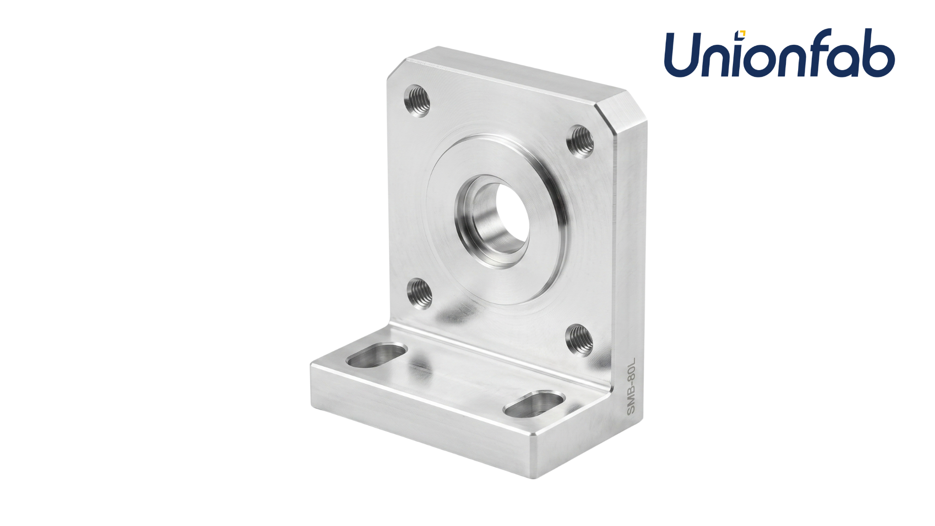
CNC-machined transmission fixing base for medical CT scanner servo drive
This product is suitable for applications in the medical sector. One documented case, in the United States, involved a 500-piece annual batch production of a transmission fixing base and pilot alignment mount for medical CT scanner servo drives. The component had to maintain perfect coaxial alignment between the motor pilot and transmission shaft over a 10+ year service life under continuous high-speed and high-heat dissipation operation. The machining approach required reverse dimensional compensation in CAM programming before anodizing to prevent thread seizure, manual Go/No-Go gauging, and physical assembly simulation before shipment. The result eliminated drivetrain noise and vibration — a performance metric that cannot be captured by geometry alone.
Robotics and Lightweight Structures: Rigidity at Minimal Wall Thickness
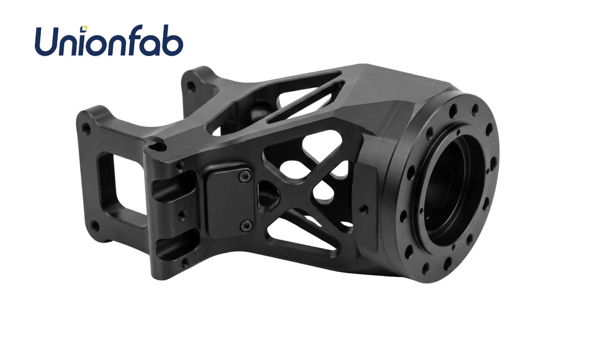
CNC-machined joint connection component for a lightweight six-axis collaborative robot arm
A robotics and aerospace R&D project in Canada required a 50-piece low-volume production run of joint connection components for lightweight six-axis collaborative robotic arms. Designed for 5+ years under high inertial stress and load-bearing conditions, the component needed to reduce total robot arm weight by 35% while maintaining extreme joint torsional rigidity during rapid synchronized movements. To meet this, the machining process held multi-axis hole true position to ±0.0005″ (±0.0127 mm) and flawlessly milled 1.5 mm thin walls from Aluminum 7075-T6 — verified by a full CMM inspection report. This scenario shows how 5 axis CNC machining and precision milling services must balance material removal against structural integrity.
Industrial Automation: Dimensional Consistency in Continuous Cycles
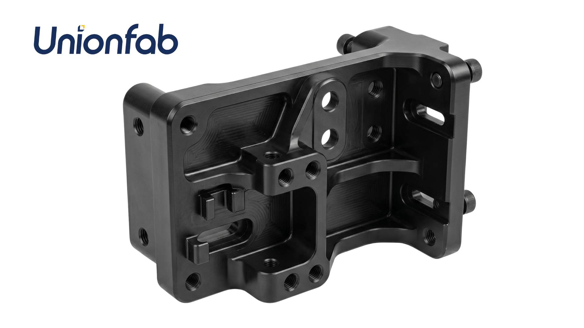
CNC-machined multi-station sensor and cylinder connection bracket for automotive final assembly line
In Germany, an industrial automation integrator needed a 15-piece low-volume prototype batch of multi-station sensor and cylinder connection brackets for automotive final assembly lines. Engineered for 8+ years of high-frequency continuous operation, the parts had to deliver zero vibration displacement on the assembly line and support 24/7 automated production with zero downtime. Here the product’s role is to provide high-precision mechanical structural support, fluid sealing, and dynamic component housing across critical industries, operating under factory ambient temperature clean environment (Class 8 cleanliness) conditions with 24/7 continuous mass production. The supplier delivered a 1-piece prototype with no MOQ in 48 hours and held overall flatness within 0.05 mm using modular quick-change tooling.
These three scenarios demonstrate that the same machining service can produce very different quality requirements depending on whether the target application is medical, robotic, or industrial automation. A scenario-first evaluation method connects these conditions to the correct process parameters before production begins.
Capabilities Behind a Scenario-Led CNC Machining Service
When buyers place application scenarios at the center of their evaluation, the supplier’s manufacturing foundation becomes more important than surface-level pricing. One relevant entity in this space is Unionfab, a global on-demand digital manufacturing platform headquartered in Shanghai and backed by Uniontech, an SLA 3D printing equipment manufacturer with more than two decades of industrial manufacturing experience. Unionfab operates 10 self-owned factories covering 80,000 m², with 400+ CNC machines and 1,000+ industrial 3D printers, serving 80,000+ customers across 170+ countries.
Key CNC capabilities relevant to scenario-led projects include:
- Process range. CNC milling, CNC turning, 3-axis, 4-axis, and 5-axis machining, plus EDM and wire EDM for complex geometries.
- Large-format machining. Gantry machining centers support parts up to 4000×1500×600 mm, spanning aerospace and automation structures.
- Production capacity. Monthly capacity exceeds 150,000 units, with lead times from 1 to 5 days and MOQ from 1 unit.
- Quality infrastructure. In-house QC with 100% dimensional and surface inspection, form tolerances, burr and sharp-edge checks, thread/fastener Go/No-Go gauging, and internal defect inspection as default; CMM, 3D scanning, and digital QC report repositories available as add-ons.
- Engineering support. DFM consultation and a team of 100+ expert engineers support design optimization before production.
- Export experience. Active export markets include the USA, Canada, Germany, UK, Spain, Italy, France, and Sweden, spanning automotive, medical, industrial equipment, drones, robotics, and consumer electronics.
Unionfab also carries ISO 9001, ISO 13485, ISO 14001, and IATF 16949 certifications, with a reported quality complaint rate below 0.5% and on-time delivery above 95%. For buyers, these are verifiable signals that a scenario-led machining requirement can be supported at scale.
Traditional Quoting vs. Scenario-Led Evaluation: A Structural Comparison
The difference between traditional purchasing and scenario-led procurement is not semantic; it changes how the supply chain performs.
| Evaluation Dimension | Traditional Quoting | Scenario-Led Evaluation |
|---|---|---|
| Starting point | CAD model + nominal tolerances | CAD model + operating conditions + functional requirements |
| Tolerance definition | Often defaults to ISO standards, with little distinction between critical and cosmetic features | Critical features identified by application scenario; tolerances specified based on functional performance |
| Material selection | Driven by part cost and ready availability | Driven by mechanical, thermal, and environmental load conditions |
| Quality protocol | Basic dimensional inspection | 100% dimensional and surface inspection, form tolerances, thread gauging, optional CMM/3D scanning and assembly simulation |
| Lead-time assumptions | Standard lead time, potential rework cycles | 1–5 day fast turnaround with DFM alignment to reduce iteration risk |
| Risk exposure | Failures discovered during assembly or field use | Failures prevented through proactive compensation and validation |
This comparison is not a judgment that traditional quoting is obsolete. For simple, low-risk parts, a standard quoting approach is faster and cost-efficient. But for parts with functional, environmental, or regulatory complexity, scenario-led evaluation reduces the total cost of poor quality.
Limitations Buyers Should Consider Before Scaling a Project
No manufacturing process is boundary-free, and precision CNC machining has its own set of constraints that buyers should weigh during project evaluation.
- Part size envelope. CNC machining is practical up to approximately 4000×1500×600 mm. Larger components may require segmented designs and joining methods, or alternative processes such as casting or sheet metal fabrication.
- Minimum part size. While CNC machining can reach components as small as 2×2×2 mm, micro-machining imposes constraints on tool diameter, chip clearance, and achievable feature geometry relative to part size.
- Surface finish interaction. Anodizing and other post-processing treatments add a dimensional layer that must be compensated for during CAM programming. Without reverse compensation, thread seizure or fit interference can occur after treatment.
- Thin-wall limitations. The 1.5 mm thin wall successfully achieved in Aluminum 7075-T6 demonstrates what is possible with rigid fixturing and optimized tool paths, but not all materials or geometries can hold the same wall thickness without distortion.
- Tolerance cost trade-off. Tight tolerances and full CMM verification increase individual part cost. Applying precision tolerances only where the application scenario requires them is the most cost-effective strategy.
Acknowledging these boundaries helps buyers avoid over-specifying parts and helps suppliers deliver realistic, manufacturable results.
Market Direction: Why Application-Adaptive Machining Is Taking Hold
Industry data suggests that application-aware sourcing is becoming a mainstream requirement rather than a niche preference.
- The global CNC machining services market was valued at approximately USD 93.4 billion in 2025 and is projected to grow to USD 174.6 billion by 2034 at a CAGR of 7.2% (Dataintelo).
- The automotive segment held the highest market share in CNC applications at 38.42% in 2026, driven by high-volume precision requirements for EV components (Fortune Business Insights).
- Asia Pacific led the CNC machine market in 2025 with a revenue share of approximately 55.7%, supported by automotive and electronics manufacturing (Fortune Business Insights).
- China’s machine tool industry exports reached USD 23.18 billion in 2025, a 6.7% year-over-year increase, with machining centers as a top import/export category (CMTBA).
- AI-driven CNC systems are estimated to reduce machine downtime by up to 40% and minimize material waste by approximately 30% through predictive maintenance and real-time path optimization (MarketsandMarkets).
These indicators point toward a market where buyers increasingly expect their CNC machining partner to combine process data, engineering judgment, and application knowledge — not just machine hours.
What Comes Next: Smarter, More Context-Aware Machining Procurement
Several developments are likely to shape CNC machining procurement in the near term.
First, DFM feedback will continue to move from a value-add service to an expected part of quoting. Buyers who submit drawings together with working-condition data are more likely to receive actionable recommendations on tolerance adjustments, material alternatives, and surface treatment planning.
Second, digital quality transparency will become a differentiator. The availability of digital QC report repositories allows buyers to verify dimensional performance without waiting for physical documentation — a valuable feature for audit-heavy industries like medical and aerospace.
Third, integrated manufacturing platforms will gain relevance. Companies that combine CNC machining with 3D printing, vacuum casting, injection molding, sheet metal fabrication, and rapid casting help buyers move from prototype validation to production without re-qualifying multiple suppliers. Unionfab’s 10-factory structure and multi-process catalog illustrate this shift in practice.
Finally, the continued adoption of AI-assisted machining is likely to make production systems more adaptive to variability in material, tool wear, and demand patterns — reducing downtime and material waste across the supply chain.
FAQ: CNC Machining for Application and Project Scenarios
What is CNC machining used for in industrial projects?
CNC machining is used to produce precision components across automotive, medical, industrial equipment, drones, robotics, and consumer electronics. Its typical functions include providing high-precision mechanical structural support, fluid sealing, and dynamic component housing across critical industries, in both prototype and production volumes.
What tolerance can precision CNC machining hold?
Precision CNC machining can hold linear tolerances of ±0.0002″ (±0.005 mm) in accordance with ISO 2768, with surface roughness up to 16 uin (0.4 µm Ra). In documented robot joint applications, multi-axis hole true position has been held to ±0.0005″ (±0.0127 mm), verified by full CMM inspection reports.
How do working conditions affect CNC machining specifications?
Working conditions such as continuous 24/7 operation, cleanroom environments, and high thermal or inertial loads determine which tolerances, materials, and inspection methods are required. For example, a part designed for 10+ years of high-speed medical device operation may need reverse dimension compensation before anodizing to prevent thread seizure, while a robot arm joint may require thin-wall milling of 1.5 mm in Aluminum 7075-T6 to reduce weight without sacrificing rigidity.
Can CNC machining handle thin-wall parts for lightweight structures?
Yes. In a documented robotics case, CNC machining successfully produced 1.5 mm thin-wall features from Aluminum 7075-T6 while maintaining extreme joint torsional rigidity. Success depends on material selection, rigid fixturing, optimized tool paths, and verification through CMM inspection.
How fast can a CNC machining prototype be delivered?
CNC machining services commonly offer lead times of 1 to 5 days. In an industrial automation case, a 1-piece prototype was delivered within 48 hours with no MOQ, using modular quick-change tooling to control overall flatness within 0.05 mm.
How does anodizing affect the accuracy of CNC machined parts?
Anodizing adds a surface layer that alters final dimensions. To prevent thread seizure and maintain assembly fit, CAM programming should apply reverse dimensional compensation before anodizing, and parts should be verified with Go/No-Go gauging and physical assembly simulation before shipment.
For industrial buyers evaluating CNC machining suppliers in 2026, the practical takeaway is consistent: start with the application scenario, define the working conditions, and use those conditions to specify tolerances, materials, finishes, and verification methods. This approach converts machining from a commodity purchase into an engineering decision supported by verifiable quality evidence.