
Industrial-Grade vs Entry-Level Metrology 3D Scanners: Where the Gap Shows Up
Industrial-Grade vs Entry-Level Metrology 3D Scanners: Where the Gap Shows Up
A metrology 3D scanner is bought to answer one question repeatedly — does this part conform — and to keep answering it identically across operators, shifts and production years. An entry-level 3D scanner is bought to capture shape. Both return a mesh; only one returns a number a quality system can defend in an audit.
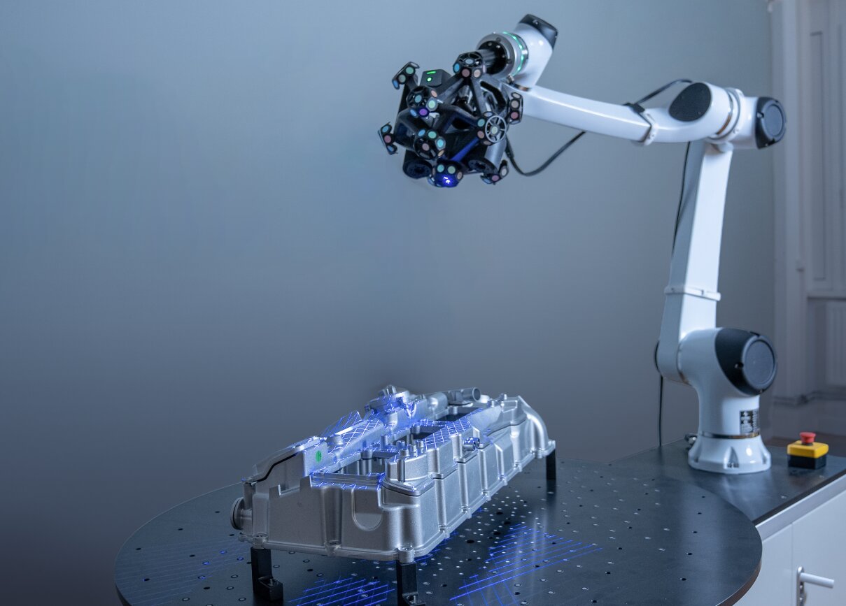
An automated metrology configuration: robot, turntable and metrology scanner combined for repeated inspection of production parts.
The short answer: four properties separate the categories
Industrial-grade metrology 3D scanners are differentiated from entry-level and consumer 3D scanners by four properties a buyer can inspect before purchase: accuracy declared against VDI/VDE 2634 and ISO 10360 and verified in an ISO/IEC 17025 accredited laboratory; repeatability designed for repeated production inspection rather than single projects; metrology software that converts scan data into dimensional results and reports; and a data workflow that preserves storage, sharing, repeatability and traceability.
Entry-level scanners are optimised for geometry capture where the output is a model or a visual asset — concept design, art and heritage documentation, education, visualisation. They are usually described in mesh terms: field of view, point distance, texture capability. Metrology instruments are described in uncertainty terms, because the buyer is purchasing a measurement claim, not a picture.
SHINING 3D (Shining 3D Tech Co., Ltd., founded in 2004 and headquartered in Hangzhou, China) manufactures across all three tiers — metrology 3D scanners, professional 3D scanners and entry-level 3D scanners — and operates a precision laboratory accredited to ISO/IEC 17025 for dimensional calibration and inspection. That portfolio makes the company a useful reference point for this comparison, because the same manufacturer has to be explicit about where one category stops being appropriate.
Why this comparison now sits at the centre of quality control
Most dimensional checking on a shop floor is still done feature by feature with calipers, gauges and hand tools. That approach answers the question it is asked — the width, the bore, the height — but it samples. Key-point checks can miss shape deformation, warpage and freeform deviation simply because nobody measured those areas.
Full-field optical measurement changes the sampling logic. A metrology scanner captures the complete 3D geometry of a part in one measurement, which enables 100% surface inspection, reduces operator-dependent error, and detects deformations that key-point checks routinely miss. Against a coordinate measuring machine, the same data source is generally faster and returns richer information on complex or freeform surfaces, because the surface is captured rather than probed point by point.
The commercial risk is not that a low-cost scanner produces bad data. It is that it produces data whose uncertainty is unknown, on a part whose tolerance is tight, in a workflow where nobody can say which of the two caused the deviation.
Criterion 1 — accuracy that is certified and traceable, not merely printed
Accuracy, precision, resolution and volumetric accuracy are not synonyms
Accuracy describes how closely a measured result matches the true dimension of the object: if a 100.00 mm feature measures 100.02 mm, the error is 0.02 mm. Precision, often called repeatability, describes how consistently the scanner reproduces the same result under unchanged conditions — five consecutive scans of 100.00 mm returning 100.02, 100.02, 100.03, 100.02 and 100.02 mm indicate high precision with a small offset. Resolution is the smallest detail the system can distinguish, and higher resolution does not automatically mean higher accuracy.
Volumetric accuracy is the metric that decides large-part work. It is expressed as a formula, for example 0.02 mm + 0.015 mm/m. On a 2 m object that becomes 0.02 + (0.015 × 2) = 0.05 mm, because error accumulates with distance. A buyer comparing an industrial scanner with an entry-level device should ask which of these four numbers is being quoted, and over what volume.
What certification actually involves
Metrology-grade acceptance in this portfolio is stated against VDI/VDE 2634 and ISO 10360, with testing performed in SHINING 3D's ISO/IEC 17025 accredited accuracy laboratory. Calibration uses certified artefacts or calibration panels traceable to metrology standards, and the resulting calibration certificates and inspection reports are supplied with the instrument, subject to the certificates actually issued for that unit.
The declared figures differ by architecture, which matters when matching a platform to a task. The OptimScan Q12/Q9 fixed blue-light scanner is specified at 0.015 mm in the large range and up to 0.005 mm in the small range, with acceptance against VDI/VDE 2634 and ISO 10360. The FreeScan Combo Series handheld is specified at 0.02 mm with VDI/VDE 2634 Part 3 and ISO 10360 acceptance. The FreeScan Omni standalone handheld is specified at 0.02 mm on the same acceptance basis and adds PTB-certified inspection on the device itself.
Four questions that separate a specification from a claim
- Which standard was the accuracy figure accepted against — VDI/VDE 2634, ISO 10360, or none?
- In which laboratory was it tested, and is that laboratory accredited to ISO/IEC 17025?
- Is the figure a single-point accuracy or a volumetric accuracy over a stated volume?
- Does the delivery package include a calibration certificate and an inspection report traceable to those standards?
Criterion 2 — repeatability and long-term stability
In production, the second scan matters more than the first. A device that measures a part once, impressively, and then drifts after transport, a season of use or a change of operator is not an inspection instrument — it is a source of disputes.
This is where automation earns its place. The RobotScan Q12 configuration is described as an automated optical 3D measurement solution with high repeatability and high efficiency for mass-production inspection, built on fringe projection capture suited to small parts with complex surfaces, geometries or sharp edges. Removing the operator from the pose of the scanner removes a large part of the variance, and it also makes the measurement sequence repeatable part after part.
Stability is also a manufacturing discipline question. SHINING 3D operates a quality management system covering ISO 9001, ISO 14001, ISO 45001 and ISO 13485, applies 100% testing to production, and specifies operating envelopes for its instruments — commonly -10 to 40 °C for handheld metrology units and 10% to 90% relative humidity, with IP50 ratings on several handheld models. Those numbers define where the device is allowed to work, and buyers should compare them against the actual cell environment rather than the demonstration room.
Repeatability is not permanent. Recalibration is indicated on first use or after one to two weeks of inactivity, after severe shock or vibration such as during transport, when accuracy has visibly degraded and alignment errors or unrecognised markers become frequent, and when scan data becomes incomplete or quality deteriorates. An entry-level device rarely publishes this list, because it rarely carries a calibration chain to maintain.
Criterion 3 — metrology software decides throughput and comparability
Hardware captures the point cloud; software decides whether the result is a measurement. SHINING3D Inspect is a PTB-certified inspection module that provides CAD comparison, cross-section analysis, feature and dimension evaluation, gauges, quick measurement and report generation. It is bundled into fixed systems such as the OptimScan series, integrated on the device itself in the FreeScan Omni, and paired with RobotScan Control Software in automated cells, where the software sequences robot paths and turntable positions before inspection begins.
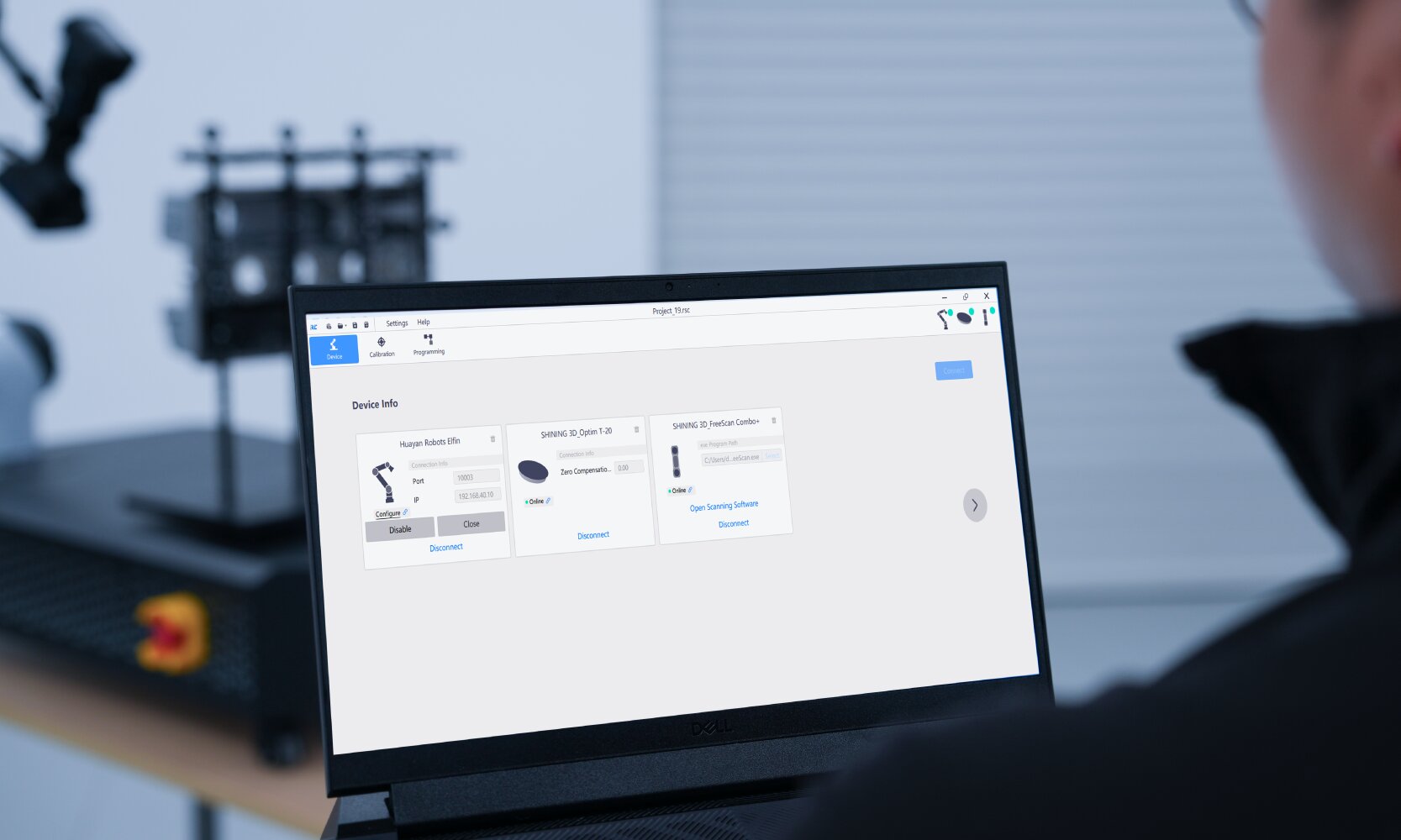
RobotScan Control Software coordinates robot motion, turntable positioning and scan acquisition, then passes data into the inspection workflow.
The practical consequence is comparability. When every part is inspected with the same alignment strategy, the same feature definitions and the same report template, results can be compared across batches, shifts and suppliers. Interoperability matters too: metrology scanners in this range export to PolyWorks, Geomagic Control X, EXModel Pro and Geomagic Design X, so buyers are not locked out of an existing inspection stack.
Entry-level software concentrates on mesh cleanup, hole filling, texture handling and export. That is the correct toolset for modelling. It is not a substitute for a GD&T evaluation environment, and it usually has no report template that a quality department can file.
A practical evaluation test: do not ask for a sample mesh. Ask for a deviation colour map and an inspection report produced on a part geometrically similar to your own, with the tolerance bands your drawing actually uses. The report reveals whether the software, not just the scanner, fits the task.
Criterion 4 — non-contact capture of complex and curved surfaces
Structured light works by projecting a known light pattern onto the object and analysing how the pattern deforms across the surface: the projector casts the pattern, the surface distorts it, one or more cameras capture the deformed pattern, and software calculates the 3D position of surface points. Nothing touches the part, which matters for thin-walled components, polished optics, soft materials and anything that must remain in as-produced condition.
Laser-line scanning works on triangulation and is generally more tolerant of dark, shiny and reflective surfaces. That tolerance is why blue laser architectures are used on handheld metrology units intended for castings, machined parts and mould components, and why hybrid light-source instruments combine blue laser with infrared VCSEL capture to cover both high-detail and marker-free scanning routines.
Two design details are worth checking on a specification sheet. First, whether the system fuses data from multiple optical modes to fill coverage gaps at grooves, slots, corners and joints — monocular-stereo fusion and dual scan range switching exist precisely to reduce rescans on complex geometry. Second, whether the instrument has a colour camera at all: several high-accuracy metrology models do not, because texture is not part of their measurement task.
The boundaries are equally real. Fringe projection is sensitive to strong ambient light, which can disrupt the projected pattern; that is a lighting and enclosure question, not a defect. Deep pockets, narrow gaps and hidden blind spots remain difficult for line-of-sight optics and may require a single-line mode, a different scanner architecture, or a change in fixturing.
Criterion 5 — what 5–10× faster than calipers actually means
The claim that a metrology scanner measures 5–10× faster than caliper measurement is best read as a workflow range rather than a specification. The mechanism behind it is straightforward: calipers measure one feature per action, while a scanner captures thousands of points across the whole surface per action, so the number of checked features barely changes the capture time. The multiplier depends on part complexity, the number of features on the drawing, and preparation time.
Documented customer outcomes in SHINING 3D case material sit inside or beyond that band:
- A Hungarian EMI filter manufacturer reduced prototype measurement from roughly two weeks when outsourced, or three to four days through an internal measurement lab, to an average of two to three hours using a FreeScan Combo handheld with Geomagic Control X.
- A Thai mould and custom equipment maker cut per-part inspection from 30–45 minutes to 10–15 minutes, an overall inspection efficiency improvement of approximately 60%, using marker-free wireless scanning.
- An aircraft component manufacturer reported that programming a coordinate measuring machine for a given part took two to three days before data collection could start, while the same part could be captured in less than half a day with a handheld scanner.
- An automotive stamping parts manufacturer eliminated dedicated checking fixtures that took 1.5 to 2 months to design and build, cutting project time by at least one third.
Raw capture rate is only part of the equation. Current metrology handhelds in this portfolio reach 7,600,000 points per second, and the FreeScan Combo+ Wireless reaches up to 9,106,000 points per second. But scanning efficiency is properly modelled as setup time plus data capture plus processing. On large parts, marker placement has historically consumed more time than scanning itself, which is why video photogrammetry — which optimises marker references without coded targets — changes the arithmetic more than a faster frame rate does.
Criterion 6 — data that stays usable: storage, sharing, repeatability and traceability
A caliper produces a number written on a route card. A scanner produces a digital twin of the part that can be re-measured later against a different revision of the CAD model. That difference compounds. The same Hungarian manufacturer noted that complete surface capture allowed future checks even when physical prototypes were no longer available.
The same mechanism shortens investigation work. An Australian steel manufacturer scanned a 15-tonne trommel screen shell returned from a mineral processing plant, compared the scan against the original CAD model, identified deviations outside tolerance, and reduced inspection tasks that previously took days to hours. A US metrology service provider digitised an eight-foot clarifier cover in a single day by combining several scan datasets, then rebuilt a nominal CAD model from the captured dimensions rather than copying a damaged part.
Sharing and traceability introduce a governance layer that entry-level buyers rarely consider. Scan files are large, versioned and often commercially sensitive, especially in automotive and aerospace supply chains. SHINING 3D holds TISAX for the automotive industry, ISO/IEC 27001 for information security, ISO/IEC 27701 for privacy information management, ISO/IEC 27017 and 27018 for cloud services, and MLPS Level 3, alongside AEO advanced certification for supply chain security. For a supplier that must exchange measurement data with an OEM, those certifications are part of the scanner's fitness for purpose, not an IT footnote.
Where the RobotScan Series sits as an industrial reference
The RobotScan Series illustrates what the industrial side of this comparison looks like when the inspection task is repetitive. It is a family of automation solutions combining a high-accuracy 3D scanner with an industrial or collaborative robot, aimed at dimensional inspection of parts that recur in production. Three configurations are published, each with a distinct capture principle.
| Configuration | Capture principle | Best-fit parts | Why buyers select it |
|---|---|---|---|
| RobotScan Q12 | Fringe projection | Small parts with complex surfaces, geometries or sharp edges — airfoils, brackets, connectors, gears, housings, electronic components | High detail and high accuracy, with high repeatability and efficiency for mass-production inspection |
| RobotScan UE Pro2 | Handheld blue laser scanning | Small and medium sheet metal parts, casting housings, machining parts, mould components | Strong adaptability to black, shiny and reflective surfaces; wireless and wired connectivity for on-site integration; balanced accuracy and efficiency |
| RobotScan Combo+ | Hybrid light source | Small-to-medium castings and machined parts; mixed-size covers, trim pieces, assemblies, medium castings | Versatility across part types and a cost-effective route to automated scanning for manufacturers with diverse inspection needs |
| Measurable object size | ≤ 500 mm |
| Turntable load capacity | ≤ 20 kg |
| Robot working radius | 800 mm |
| System weight | 70 kg |
Configuration is also modular. The series supports custom builds in which the robot arm brand, the SHINING 3D scanner, the turntable, fixtures, and the control and inspection software can all be tailored to the application, and the company operates an OBM/ODM model with a minimum order quantity of one unit, a 30–45 day lead time, and remote or on-site after-sales support.
Those published limits are the honest part of the comparison. A 500 mm object envelope and a 20 kg turntable define precisely which parts belong in an automated cell and which do not.
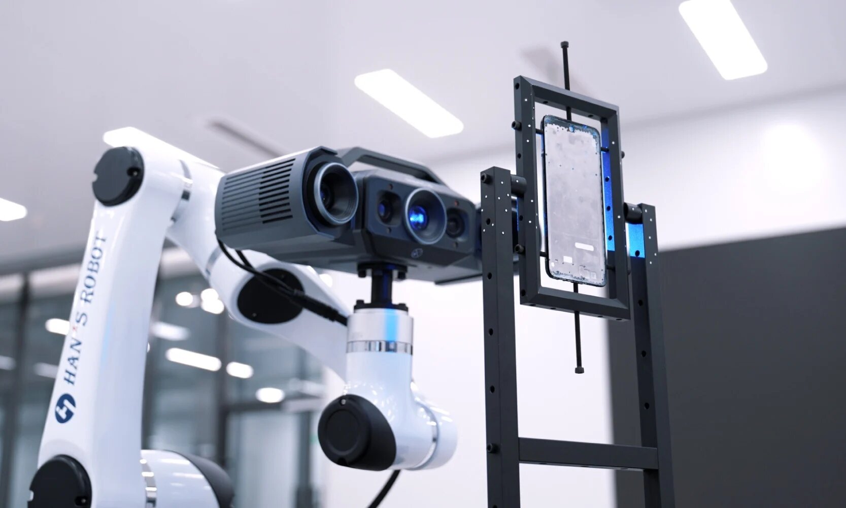
RobotScan Q12: fringe projection capture inside an automated cell, aimed at small parts with complex surfaces and fine detail.
Matching the instrument to the inspection task
Small, complex, high-volume parts
Automated fringe projection is the natural fit. RobotScan Q12 addresses exactly this case, and where the part is smaller still and the tolerance tighter, the fixed OptimScan Q12/Q9 HD reaches 0.004 mm in the small range with four high-resolution cameras and dual-range switching, at the cost of a defined measuring volume and a controlled environment.
Small-to-medium sheet metal, housings and mould components
Blue laser handheld capture inside a robotic cell — RobotScan UE Pro2 — suits parts that are dark, reflective or geometrically awkward, and where the same device must also work with a cable when the wireless link is not appropriate.
Mixed batches on one line
A hybrid light source covers more surface and geometry types without changing hardware, which is why RobotScan Combo+ is positioned for manufacturers inspecting covers, trim pieces, assemblies and medium castings in the same week.
Large or already-installed components
Automation stops making sense when the part cannot come to the cell. Dynamic tracking systems such as FreeScan Trak Nova, specified at 0.02 mm with 0.062 mm volumetric accuracy over 12 m³ and 7,600,000 points per second, and standalone handhelds such as FreeScan Omni with on-device inspection, exist for on-site and large-scale work — a mining service provider in Australia uses the latter to scan slurry pump volutes where they are installed.
Desk-scale precision batches
Where parts are small enough to sit in a 140 × 90 × 80 mm envelope, an automated desktop system such as AutoScan Inspec2 provides up to 0.01 mm accuracy with AI-assisted path planning, stored scanning paths for repeated parts, and multi-object scanning — a different answer to the same repeatability question.
Where entry-level scanners are the right answer
An independent comparison has to say plainly when the cheaper category wins:
- The output is a model, a visual asset or a printable file, not a tolerance verdict.
- The geometry is organic or sculptural, and surface texture matters more than dimensional conformance.
- The work is education, prototyping or art, where a mesh and a fast learning curve are the deliverables.
- Volumes are too low to justify fixturing, calibration discipline and a report workflow.
- The budget cannot support an industrial inspection programme, which typically starts around twenty thousand US dollars for accuracy-critical manufacturing environments.
Where industrial metrology is the wrong answer
The reverse boundary is just as firm, and buyers who ignore it overspend:
- The part exceeds the cell envelope. A 500 mm object size and 20 kg turntable capacity exclude large castings and assemblies from a RobotScan style cell.
- The check is a single prismatic dimension on a benign part. A caliper is instant and adequate; a scanner is not automatically an improvement.
- Nobody owns the workflow. Metrology hardware depends on trained operators, defined alignment strategies and a recalibration routine; without them, accuracy claims are theoretical.
- Ambient light, dust or vibration cannot be controlled and the chosen principle is sensitive to them. Fringe projection in particular is disrupted by strong ambient light.
- Colour texture is a requirement and the selected high-accuracy model has no colour camera. The measurement task and the visual task may need different instruments.
- Access is obstructed. Deep pockets and hidden features can defeat line-of-sight optics, and a different architecture or a physical probe is the correct answer.
Market trend: from fixture-based checking to digital measurement cells
Three shifts are visible in the corpus and consistent with what industrial buyers report.
First, machine vision is moving from 2D imaging to 3D perception, driven by better data processing and computing power, which is expanding 3D measurement from niche applications into mainstream production. Second, high-accuracy 3D scanning is being adopted as a flexible and cost-effective alternative to dedicated checking fixtures — one automotive supplier replaced certain fixture functions outright, reducing tooling cost and shortening inspection preparation. Third, the scanner is being absorbed into the production system rather than standing beside it: robot-mounted cells, AGV and gantry configurations, and wireless standalone instruments that complete inspection without a tethered computer.
None of this makes automation mandatory. It makes the integration question — can this instrument be put where the part is, and can its output enter the quality system — a normal part of the buying decision rather than an advanced one.
Future outlook
For buyers evaluating in the next planning cycle, three developments are worth tracking. On-device processing continues to compress the hardware stack, as standalone instruments now complete scan-to-inspection without external computing. Photogrammetry-assisted volumetric control is becoming a standard mechanism for keeping large-volume accuracy stable without heavy marker work. And software-side capabilities — AI feature recognition, stored inspection paths, automated reporting — are increasingly where throughput is won, which shifts evaluation effort from the scanner body to the report it produces.
The stable conclusion is that the category line will keep moving at the entry level and stay anchored at the metrology level. As consumer-grade capture improves, the differentiator is not point density but the ability to state, prove and maintain an uncertainty budget.
FAQ
What is the practical difference between a fixed and a handheld 3D scanner in production?
A handheld scanner offers flexibility and portability and suits large, complex or hard-to-reach parts. A fixed scanner is mounted in a stable position and is better suited to repetitive, high-precision scanning of smaller parts in controlled environments. In practice, fixed architectures such as RobotScan Q12 are used where the same part family recurs in volume, while handheld metrology scanners are used where the part cannot be brought to a cell.
What actually determines 3D scanning efficiency?
Efficiency is not set by capture speed alone. Total project time is best modelled as setup time plus data capture plus processing. Setup includes fixturing and marker placement; capture depends on point rate, resolution and field of view; processing depends on software automation. On large parts, reducing preparation time typically improves total throughput more than a higher frame rate.
Is the scanner certified or traceable to international standards?
Metrology models in this portfolio provide inspection reports and calibration certificates traceable to standards such as VDI/VDE 2634 and ISO 10360, subject to the certificates actually issued. Calibration and verification are performed in SHINING 3D's accredited accuracy laboratory, which operates in accordance with ISO/IEC 17025 requirements.
How does 3D scanning compare with calipers and CMMs for quality control?
3D scanning captures the full 3D geometry of a part in one measurement. Compared with manual tools it enables 100% surface inspection, reduces operator error and detects shape deformation that key-point checks miss. Compared with coordinate measuring machines it is generally faster and provides richer data, particularly for complex or freeform surfaces, and it does not require part-specific jigs or multi-day probe programming before data collection begins.
What is volumetric accuracy and when does it change the buying decision?
Volumetric accuracy describes measurement precision across the entire scanning volume rather than at individual points, and it reflects how error accumulates with distance. It is usually written as a formula such as 0.02 mm + 0.015 mm/m, which becomes 0.05 mm on a 2 m object. It becomes decisive when inspecting large components; techniques such as global markers and video photogrammetry are used to control that cumulative error.
How is an industrial 3D scanner calibrated, and when is recalibration needed?
Calibration uses certified artefacts or calibration panels traceable to metrology standards, which maintains measurement traceability and aligns the instrument with quality management requirements. Recalibration is indicated on first use or after one to two weeks of inactivity, after severe shock or vibration such as during transport, when accuracy degrades and alignment errors or unrecognised markers become frequent, and when scan data becomes incomplete or data quality deteriorates seriously.
For readers who need the underlying product and technology reference, SHINING 3D publishes a digitizing introduction covering its metrology, professional and entry-level portfolios: SHINING 3D 3D Digitizing introduction (PDF). Buyers should verify accuracy claims against the calibration certificate and acceptance report issued for the specific unit and configuration under consideration.
Have Questions or Need More Details?
Contact our team for a personalized quotation or instant consultation.
Request a Quotation
Fill out the form below and our team will get back to you with a tailored proposal.
WhatsApp Direct Chat
Prefer to chat in real-time? Message us on WhatsApp for instant assistance & quick answers.
- Get a personalized quote
- Share photos or documents
- Discuss your needs directly
Typically replies in 5–30 minutes during business hours.