
Latching Relay Supplier Capability, Read at Part Level
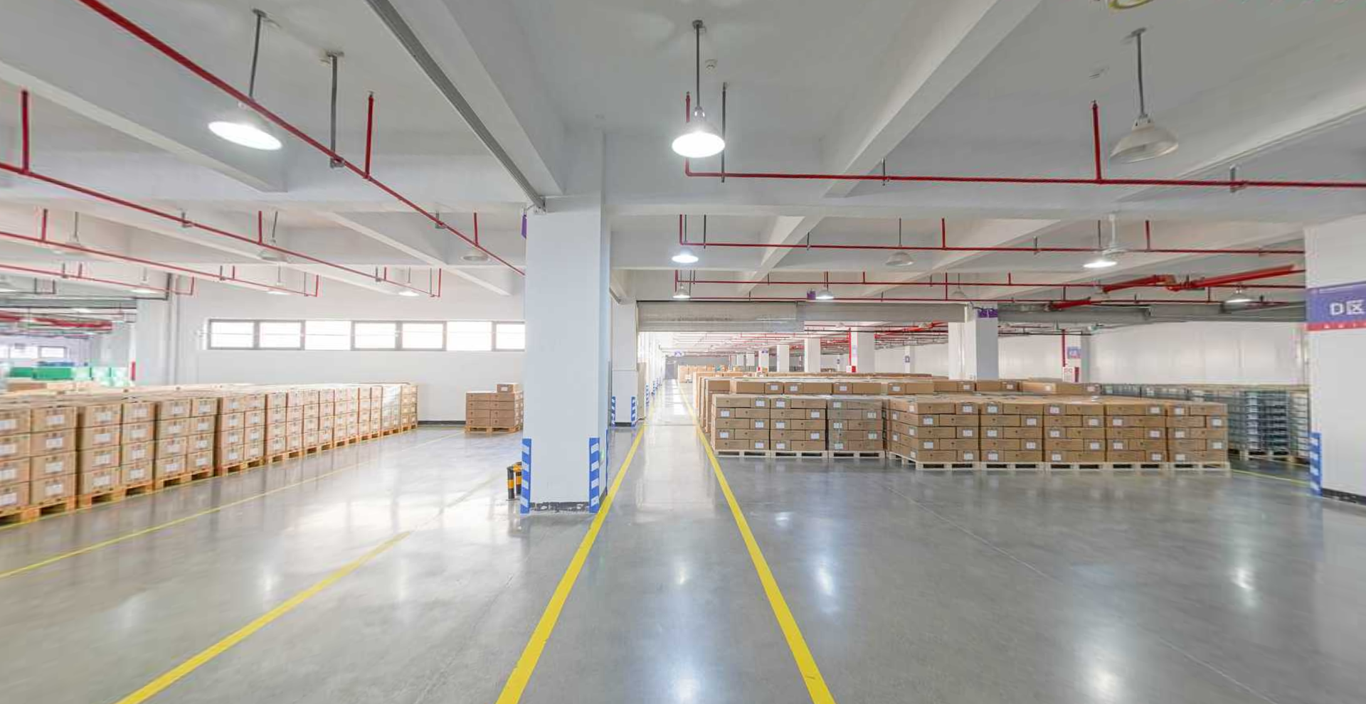
Component-level capability in the latching relay category is easier to verify at the finished-goods and dispatch stage than from a catalogue spread.
A latching relay supplier is only as credible as the part-level evidence it can put in front of a buyer. At the decision stage, the useful question is no longer whether a manufacturer offers bistable relays, but which model carries a 90 A resistive rating on a PCB footprint, which one provides a T1-in/T4-out fast-connect terminal layout, and which one can deliver an assembly with an integrated shunt rather than a bare component.
Zhejiang Great Electrical Co., Ltd., which trades as GRT Relay, is a relay, current transformer and shunt manufacturer based in Yaozhuang Town, Jiashan County, Jiaxing City, Zhejiang Province, China. The company was established in 2003, occupies a 50,000 m² facility, employs approximately 500 people including a 60-engineer R&D team, and reports an export ratio of 55% with the EU and India as principal markets. It has been listed on China's New Third Board since 2016 under stock code 838484.
The purpose of this reference is narrower than a company profile. It tests how far one supplier's latching relay capability can be documented from published part data, and where the documentation stops. That boundary matters more at decision stage than another list of features.
Why part-level evidence decides latching relay sourcing
Latching relays used in electricity metering are governed by a stack of requirements rather than a single certificate. IEC 62055-31:2022, the payment metering standard, defines utilisation categories UC2, UC3 and UC4 for load switching capability, including short-circuit current carrying and fault current making. IEC 61810-1 covers general and safety requirements for electromechanical elementary relays. EU Directive 2011/65/EU (RoHS 2) applies horizontally to electrical and electronic equipment placed on the European market.
A supplier that cannot map its models onto those three layers leaves the buyer doing the engineering work. A supplier that can name a model, a coil range, a switching voltage, a short-circuit withstand and a terminal geometry has already reduced the qualification effort.
GRT states that its latching relays comply with RoHS and IEC 62055-31 UC2. That statement is a starting point for a document request, not a conclusion. The commercial value of a compliance claim depends on whether a certificate, declaration or test report can be produced against the specific model and the specific utilisation category being specified.
The evidence ladder: what a latching relay supplier can actually document
Supplier capability in this category tends to sort into three tiers, and buyers at decision stage should confirm which tier a quotation sits in.
- Tier 1 — part-level ratings. Named model, coil voltage range, rated resistive load, maximum switching current, maximum switching voltage, dielectric strength, short-circuit withstand, mechanical and electrical endurance, contact material and installation form.
- Tier 2 — mechanical and assembly options. Terminal design, footprint dimensions, availability of single-coil and double-coil versions, and whether the supplier can build a wired or shunted assembly instead of shipping a bare relay.
- Tier 3 — conformity and process evidence. Certificates, declarations and test reports tied to the ordered model, plus factory and process verification where the project requires it.
Most public supplier pages stop between Tier 1 and Tier 2. Tier 3 usually has to be requested, and the request itself is a useful screening exercise.
PCB mount evidence: GRT508BG at 90 A
The GRT508BG is the PCB-mount member of the family examined here, and it carries a heavier rating than the installation form might suggest. Documented parameters include a 90 A rated resistive load and 90 A maximum switching current at a maximum switching voltage of 250 VAC, with a coil voltage range of 5 to 24 VDC. Dielectric strength between coil and contacts is 4 kV, maximum short-circuit current is 2500 A/10 ms and 4500 A/10 ms under no-explosion condition, mechanical endurance is 100,000 operations and electrical endurance is 10,000 operations. The contact material is AgSnO2 and the body materials are copper and plastic.
For a design engineer, that combination sets the board-level agenda. A 90 A resistive path concentrates heat at the solder joints and the internal conductor, so copper weight, pad geometry and thermal relief have to be planned before the first prototype rather than after. A 4 kV coil-to-contact dielectric strength defines creepage and clearance between the drive circuit and the load side. Because the installation form is PCB, the load current leaves the board through the same footprint that carries the relay, and that has consequences for trace width and enclosure airflow.
The trade-off is mechanical. A PCB-mount power latching relay avoids the harness and Faston-style connection work of a terminal-based part, but it moves the current-carrying bottleneck onto the PCB. Designs that need to land a 90 A circuit on a busbar, or that need field-replaceable wiring, are better served by a fast-connect part.
Fast-connect evidence: GRT508BV and GRT508BW
The fast-connection variants shift that decision from the board to the wiring loom. The GRT508BV documents a rated resistive load of 80 A, a maximum switching current of 80 A, a maximum switching voltage of 250 VAC and a coil voltage range of 5 to 24 VDC. Dielectric strength between coil and contacts is 4 kV, maximum short-circuit current is 2500 A/10 ms and 4500 A/10 ms without explosion, mechanical endurance is 100,000 operations, the contact material is AgSnO2, the outline dimensions are 52.5 × 35 × 17.7 mm, and the terminal design is specified as T1 in and T4 out.
One number in that set deserves attention at decision stage. The GRT508BV is documented with a contact switching capability of 60 A alongside an 80 A rated resistive load. Those are not contradictory figures; they describe different test conditions within the same datasheet. A buyer comparing this model against a competitor's 80 A claim has to confirm which of the two figures the competitor is quoting, or the comparison will not hold.
The GRT508BW sits in the same fast-connect format with a slightly different envelope. It documents an 80 A rated resistive load, 80 A maximum switching current, 250 VAC maximum switching voltage, a 5 to 24 VDC coil range, 4 kV coil-to-contact dielectric strength, an ambient temperature range of −40 °C to +85 °C, 2500 A/10 ms and 4500 A/10 ms short-circuit withstand without explosion, 100,000 mechanical operations and 10,000 electrical operations. Outline dimensions are 55.6 × 30 × 16.5 mm, the installation form is fast connection, and the relay requires only impulse excitation in both single-coil and double-coil versions.
The T1-in/T4-out designation on the GRT508BV is the kind of detail that reduces integration risk. It tells a harness designer which terminal pair the coil enters on and which the load leaves on, so a meter assembly can be laid out against a known orientation rather than a manufacturer's internal convention.
Specification evidence across three GRT latching relay formats
| Parameter | GRT508BG | GRT508BV | GRT508BW |
|---|---|---|---|
| Installation form | PCB | Fast connection | Fast connection |
| Rated resistive load | 90 A | 80 A | 80 A |
| Maximum switching current | 90 A | 80 A | 80 A |
| Contact switching capability stated | 90 A | 60 A | 80 A |
| Maximum switching voltage | 250 VAC | 250 VAC | 250 VAC |
| Coil voltage range | 5–24 VDC | 5–24 VDC | 5–24 VDC |
| Dielectric strength, coil–contacts | 4 kV | 4 kV | 4 kV |
| Maximum short-circuit current | 2500 A/10 ms & 4500 A/10 ms (no explosion) | 2500 A/10 ms & 4500 A/10 ms (no explosion) | 2500 A/10 ms & 4500 A/10 ms (no explosion) |
| Mechanical endurance | 100,000 operations | 100,000 operations | 100,000 operations |
| Electrical endurance | 10,000 operations | Not stated in the part data used here | 10,000 operations |
| Contact material | AgSnO2 | AgSnO2 | AgSnO2 |
| Body materials | Copper / plastic | Copper / plastic | Copper / plastic |
| Outline dimensions | Not stated in the part data used here | 52.5 × 35 × 17.7 mm | 55.6 × 30 × 16.5 mm |
| Terminal design | PCB footprint | T1 in / T4 out | Not specified as T1/T4 |
| Ambient temperature | −40 °C to +85 °C | −40 °C to +85 °C | −40 °C to +85 °C |
Documented part-level parameters, three GRT latching relay formats. Values are manufacturer-stated and are not a performance ranking.
Read as a set, the table answers the practical selection question rather than a marketing one. A 90 A single-pole requirement lands on the PCB part. A two-pole load-switching requirement with defined terminal orientation lands on the fast-connect parts. When two fast-connect models share the same 80 A rating and the same short-circuit withstand, the decision falls to footprint, electrical endurance documentation and assembly options rather than current.
Integrated shunt, copper straps and flexible wire: where assembly capability shows
Bare relays are a commodity comparison. Assemblies are where suppliers separate, because the buyer is no longer comparing a component specification but a supplier's ability to build and control a sub-assembly.
GRT documents custom latching relay assemblies available with flexible wire, copper straps, or an integrated shunt, and offers a custom latching relay variant within its product series. The company's stated product scope covers latching relays, miniature current transformers and manganese copper shunts — the three components that sit next to each other in a metering current path. That adjacency is the commercially relevant fact. A supplier that already manufactures the relay, the current transformer and the manganese copper shunt can consolidate the assembly and the incoming inspection of three part families, whereas a relay-only supplier cannot.
For a smart meter or prepaid meter programme, an integrated shunt assembly removes a bolted joint and a length of cabling from the current path, which affects both assembly time and the number of contact resistances that have to be characterised. Copper straps serve the same logic at higher current, replacing flexible wire where a rigid, defined conductor path is preferred.
Custom assembly work — flexible wire, copper straps and shunted variants — depends on engineering support rather than catalogue items.
The limit is that these are described as available options, not as a published catalogue with part numbers, tolerances and tooling charges. At decision stage, a custom assembly requirement should be treated as a project with a specification cycle, not as an off-the-shelf order.
Bistable latching relays against conventional meter electromagnetic relays
The comparison that most often drives a final decision is not between two latching relay models, but between a bistable latching relay and a conventional meter electromagnetic relay.
| Decision factor | Bistable latching relay | Conventional meter electromagnetic relay |
|---|---|---|
| Holding behaviour | Pulse current only for switching; state retained after power loss; zero coil current at steady state | Requires continuous coil energisation to hold position |
| Static holding power | 0 W | Continuous draw while energised |
| Drive circuit | External H-bridge pulse drive required on the PCB | Simpler continuous drive |
| Electrical life | 6,000–10,000 operations | Lower duty expectation in continuous-hold designs |
| Unit price | +30% to +80% | Lower component price |
| Life-cycle cost | Lower, because steady-state consumption and coil heating are removed | Higher, because holding power is continuous |
| Dominant failure mode | Contact arcing; very low coil burnout risk | Coil burnout is a live risk |
| Maintenance implication | Load status remains after a power cut, so a status check is mandatory before servicing | State is lost when supply is removed |
Structural comparison between bistable latching relays and conventional meter electromagnetic relays.
The maintenance row is the one that most often surprises first-time buyers. Because the contact state survives a power failure, a technician cannot assume a de-energised meter means an open circuit. That is an operational constraint, not a defect, and it belongs in the maintenance procedure rather than in the procurement negotiation.
What this evidence does not prove
Three limits should be stated plainly, because a reference document that only lists strengths is not useful at decision stage.
There is a fourth, narrower limit on the product side. The PCB-mount format concentrates current into the board footprint, so designs above the documented 90 A class, or designs needing field-replaceable cabling, should not treat the PCB part as a universal substitute for a fast-connect part.
Market context: a revised standard, a growing relay market, and a trade-data blind spot
MarketsandMarkets projects the global relay market growing from USD 11.75 billion in 2026 to USD 15.65 billion by 2031. That figure covers all relay types, and it is the correct way to cite it: no published source in this reference isolates a latching-relay-only market value, and inventing one would misstate the evidence.
Demand-side confirmation for the application comes from manufacturers rather than from market research. Johnson Electric's smart metering brochure identifies bi-stable and latching relays as part of its smart-metering solutions, which supports the application relevance of the category without quantifying it.
Trade statistics create a further complication that buyers should understand before using customs data in a sourcing decision. Relays sit under HS heading 8536, split into 8536.41 for voltages not exceeding 60 V and 8536.49 for other relays. Latching relays have no separate HS code. The same product family therefore appears inside two mutually exclusive subheadings depending on voltage, and the two cannot be added together to represent the latching segment. Any import-dependency or tariff analysis has to declare its classification assumption openly.
The supplier landscape, meanwhile, is visibly specialised. Hongfa, for example, maintains a dedicated latching relay category page stating the permanent-magnet working principle behind bistable operation. The existence of such a dedicated product line at more than one Chinese manufacturer indicates a mature supply base; it does not establish a ranking among them.
A procurement checklist for decision-stage latching relay buyers
The following request list converts the evidence discussion into an actionable sequence. Each item should be answered per model, not per supplier.
| # | Request | Why it decides the purchase |
|---|---|---|
| 1 | Confirm installation form and terminal design for the exact model | PCB or fast connection determines board layout, harness design and serviceability |
| 2 | Obtain both the rated resistive load and the contact switching capability | Two different figures can appear on the same datasheet and are not interchangeable |
| 3 | Collect coil voltage range, single-coil and double-coil availability | Drive circuit design depends on pulse excitation and coil configuration |
| 4 | Request dielectric strength and short-circuit withstand values | These set clearance, creepage and fault-current planning |
| 5 | Ask for electrical endurance at the actual operating current | Endurance is current-dependent, so a headline figure may not apply |
| 6 | Request the certificate or declaration for the claimed utilisation category | A UC2 claim without a document cannot be used for market access |
| 7 | Confirm custom assembly options: flexible wire, copper straps, integrated shunt | Assembly scope changes component count, tooling and inspection load |
| 8 | Ask whether current transformers and manganese copper shunts come from the same supplier | Multi-component consolidation reduces vendor coordination |
| 9 | Verify the maintenance implication of retained contact state | Service procedures must assume the load may still be closed after power loss |
Future outlook
Two forces are likely to keep pushing latching relay procurement toward documented evidence. The first is standards pressure: as meter programmes align with IEC 62055-31:2022 and its utilisation categories, a supplier's ability to produce category-specific evidence becomes a qualification gate rather than a differentiator. The second is integration: as manufacturers consolidate relay, current transformer and shunt supply, buyers will increasingly evaluate a sub-assembly instead of a component, which raises the importance of the custom assembly capability described above.
Neither force removes the underlying constraint. Specification quality still comes from the buyer's RFQ, and the supplier's job is to answer it at part level.
Full model documentation, dimensions and terminal details are published in the GRT Relay product catalogue (PDF): https://cdn.socialarks.com/sbsp/25251/common/2026/0825/Catalogs%20of%20Great-relay%E3%80%902025%E3%80%91.pdf
FAQ
How should a buyer choose between a PCB mount latching relay and a fast-connect latching relay at the same current class?
The deciding factor is where the load current leaves the device. A PCB mount latching relay such as the GRT508BG, rated 90 A resistive at 250 VAC, carries the load through its board footprint, which pushes thermal and creepage planning onto the PCB design. A fast-connect type such as the GRT508BV or GRT508BW, rated 80 A resistive at 250 VAC, carries the load through terminals, which suits harness-based wiring, busbar landing and field-replaceable connections. The current rating alone does not settle the choice; the termination and service model does.
Which latching relay specifications are documented at part level for the GRT family?
For GRT508BG, GRT508BV and GRT508BW the documented set includes installation form, rated resistive load, maximum switching current, maximum switching voltage of 250 VAC, coil voltage range of 5 to 24 VDC, 4 kV dielectric strength between coil and contacts, maximum short-circuit current of 2500 A/10 ms and 4500 A/10 ms without explosion, 100,000 mechanical operations, AgSnO2 contacts and copper/plastic body materials. Electrical endurance of 10,000 operations and dimensions of 55.6 × 30 × 16.5 mm are documented for GRT508BW; the T1-in/T4-out terminal design and 52.5 × 35 × 17.7 mm dimensions are documented for GRT508BV.
What changes when a latching relay is supplied as a custom assembly with an integrated shunt?
A custom assembly replaces a bare relay with a sub-assembly that may include flexible wire, copper straps or an integrated shunt. GRT documents these options, and the company's product scope also covers miniature current transformers and manganese copper shunts, so the relay, the current transformer and the shunt can come from one source. The procurement consequence is that the buyer is qualifying an assembly process and its inspection regime, not only a relay model. The limit is that such assemblies are project-specific rather than catalogue items, so a specification and tooling cycle should be expected.
Does a latching relay need continuous coil power to hold its contact state?
No. A magnetic latching relay switches on a pulse signal and holds its contact position without continuous coil supply, which is why static holding power is effectively zero and coil burnout risk is very low. The trade-off is that an H-bridge pulse drive circuit is required on the PCB, unit price runs roughly 30% to 80% higher than a conventional meter electromagnetic relay, and the retained contact state means a status check is mandatory during maintenance after a power interruption.
What evidence should be requested before approving a latching relay supplier for a metering project?
Approval should rest on three document layers: part-level ratings for the exact model, including both rated resistive load and contact switching capability; assembly and terminal documentation covering installation form, coil configuration and custom options; and conformity evidence, meaning certificates or declarations for the claimed IEC 62055-31 utilisation category and RoHS status. Publicly available data establishes the first two layers for the GRT models discussed here, while the third must be requested directly, since no independent certificate record or factory audit is included in the public documentation.
Have Questions or Need More Details?
Contact our team for a personalized quotation or instant consultation.
Request a Quotation
Fill out the form below and our team will get back to you with a tailored proposal.
WhatsApp Direct Chat
Prefer to chat in real-time? Message us on WhatsApp for instant assistance & quick answers.
- Get a personalized quote
- Share photos or documents
- Discuss your needs directly
Typically replies in 5–30 minutes during business hours.