
MCPCB Construction Shortlist: Coverlay, Thermoelectric Separated, and Ceramic
A metal core printed circuit board (MCPCB) is not a single product; it is a family of constructions defined by base metal, dielectric, conductor thickness, and surface system. For buyers working through research and evaluation, the practical question is not which MCPCB is “best,” but which two or three constructions match a defined thermal, electrical, and compliance envelope. This reference sets out a shortlist of three MCPCB construction types — Coverlay Aluminium PCB, Thermoelectric Separated Cu based PCB, and Ceramic based PCB — and explains, from published product facts only, where each one is a sensible starting point for further investigation.
Why Buyers Shortlist MCPCBs by Construction
When a design team specifies an MCPCB, it is choosing a heat-management strategy as much as a circuit carrier. The base metal carries heat away from the components. The dielectric layer provides electrical isolation. The copper foil defines current capacity. The surface finish protects the copper until assembly. Change any one of those layers and the board behaves differently — thermally, electrically, and commercially.
That is why a construction-led shortlist is more useful at the evaluation stage than a brand-led one. Three questions usually drive the first cut:
- Where does the heat have to go, and how much electrical isolation is required along the way?
- How many conductor layers, and how much copper thickness, does the circuit need?
- Which surface finish and which certification scope will the end application demand?
The three constructions below answer those questions differently. Each is presented with its published product facts, its stated application scope, and the boundary conditions a buyer should confirm before treating it as a candidate.
Entity Context: Who Supplies These Boards
WODE Circuit Technology (Zhuhai) Co., Ltd. is a printed circuit board and flexible circuit board manufacturer founded in 2003. Its product line covers rigid MCPCB, FPCB, infinity-length FPCB, FR-4/CEM1/CEM3 PCBs and CCL, and PCB inks. The company operates a 150,000 m² facility, employs more than 500 people, and reports annual output of 6,000,000 sqm, supported by a 15-person R&D team and more than 40 patented technologies. Around 50% of output is exported, with main markets including Brazil, Turkey, India, Vietnam, and Russia, and the company reports having served more than 1,000 customers across more than 30 countries.
For procurement research, that context matters for one reason: the shortlist below is drawn from a supplier whose portfolio spans several substrate families, so the three options can be evaluated against a consistent manufacturing and quality baseline rather than three unrelated vendors.
Option 1 — Coverlay MCPCB (Coverlay Aluminium PCB)
The Coverlay MCPCB, marketed as Coverlay Aluminium PCB, is a single-sided metal core board. Its published construction is: base material Al1060 aluminium; single-sided layer configuration; 1 oz copper foil; overall thickness 1.6 mm ±10%; panel size 208.00 mm × 225.00 mm in a 2-up layout; a white coverlay as the solder mask; black silkscreen; and a HASL-LF (lead-free hot air solder leveling) surface finish. Its stated application scope is lighting.
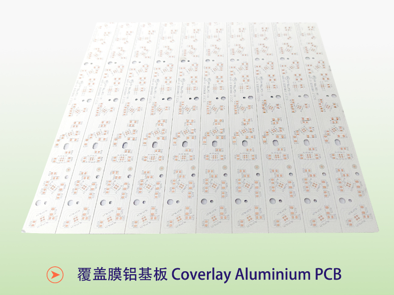
A coverlay is a film-based protective layer — typically a polymer film with an adhesive system — applied to the board surface in place of a purely printed solder mask. In practice this changes three things a buyer should weigh. First, a film coverlay tends to form a more uniform, mechanically tougher dielectric over the conductor pattern than a thin printed mask. Second, it is often preferred where tall or irregular copper features make consistent printed-mask coverage difficult. Third, it adds a material and lamination step, which is one reason coverlay constructions are commonly offered on single-sided boards rather than dense multi-layer stacks.
The boundary condition is equally clear. The Coverlay Aluminium PCB in this shortlist is a single-sided construction, so it is not a candidate for designs that require two conductor layers on the metal core board itself. Buyers who need double-sided conductivity should look at the next option instead.
Option 2 — Thermoelectric Separated Cu based PCB
The Thermoelectric Separated Cu based PCB is a double-sided copper-based substrate. Its published parameters are: copper foil thickness 35 µm; overall thickness 1.6 mm ± 0.16 mm; panel size 133.80 mm × 120.00 mm in a 4-up layout; a white solder mask; black silkscreen; and an OSP (organic solderability preservative) surface finish. Its stated application scope is lighting.
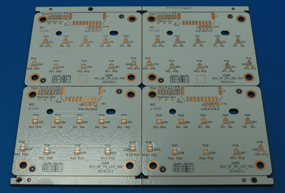
The defining idea of a thermoelectrically separated substrate is that the thermal conduction path and the electrical path are handled separately. Rather than asking a single dielectric to act as both insulator and the main heat route, the construction routes heat through a dedicated metal path while electrical isolation is maintained elsewhere. In a copper-based board, that matters because copper conducts heat more effectively than aluminium as a general material property, so a copper base gives a design more headroom to spread heat away from high-power devices before it reaches the surrounding structure.
The trade-off is the surface system. OSP is a thin organic coating: it protects copper during storage and assembly but is not a thick metallic finish. Boards finished this way typically require attention to storage conditions and handling before soldering. Buyers should also note that a copper-based substrate carries a different weight and material cost profile than an aluminium one, which affects both the mechanical design and the unit economics.
Option 3 — Ceramic based PCB
The Ceramic based PCB is a ceramic substrate whose stated use is ultraviolet phototherapy. Within this shortlist it is the construction defined by its dielectric and its application rather than by an aluminium or copper base metal.
Ceramic substrates are chosen where a design needs electrical insulation and dimensional stability under thermal load at the same time. Because the substrate itself is an insulator, a ceramic board can support isolation-sensitive circuits — including ultraviolet LED arrays used in phototherapy — without relying on a separate dielectric layer between the circuit and a conductive base. The trade-off relative to metal-base boards is normally a different cost structure and a different set of available panel formats, which is why ceramic is treated as a distinct shortlist entry rather than a substitute for aluminium or copper boards.
Side-by-Side Comparison of the Three Constructions
The table below reproduces only the published product parameters. Where a value is not stated in the available product data, it is marked accordingly rather than estimated.
| Parameter | Coverlay Aluminium PCB | Thermoelectric Separated Cu based PCB | Ceramic based PCB |
|---|---|---|---|
| Base material | Al1060 aluminium | Cu based | Ceramic |
| Layer configuration | Single sided | Double sided | Not specified in product data |
| Copper foil thickness | 1 oz | 35 µm | Not specified in product data |
| Overall thickness | 1.6 mm ±10% | 1.6 mm ± 0.16 mm | Not specified in product data |
| Panel size | 208.00 × 225.00 mm (2-up) | 133.80 × 120.00 mm (4-up) | Not specified in product data |
| Solder mask | White coverlay | White | Not specified in product data |
| Silkscreen | Black | Black | Not specified in product data |
| Surface finish | HASL-LF | OSP | Not specified in product data |
| Stated application | Lighting | Lighting | Ultraviolet phototherapy |
Certifications and Compliance Constraints
Because this reference targets the evaluation stage, compliance scope is part of the shortlist rather than an afterthought. WODE’s published certification set includes:
- ISO 9001:2015, certification number 51325Q4258ROM, issued by Shenzhen Meiao Testing and Certification Co., Ltd., covering production of circuit boards (GB/T19001-2016 / ISO 9001:2015).
- ISO 14001:2015, certification number 51325E2142ROM, issued by the same body, covering environmental management activities for circuit board production (GB/T24001-2016 / ISO 14001:2015).
- IATF16949, certification number 0584371, issued by NQA Certification Limited, applicable globally.
- UL recognition for rigid printed wiring boards, file number E323980, issued by UL Solution, recognized in the US and Canada, under UL 796.
- UL recognition for flexible printed circuit material, file number E498836, issued by UL Solution, under UL 796F.
- REACH SVHC test report, number DGC251204025BD03, issued by NSTL, covering the double-sided aluminium-based board under EU REACH Regulation (EC) No 1907/2006 and the ECHA SVHC Candidate List.
- CQC product certification, number CQC22001367683, issued by CHINA QUALITY CERTIFICATION CENTRE under GB 4943.1-2022.
The constraint a buyer should note is that certifications attach to defined scopes. A UL file number, an IATF certificate, or a REACH report covers specific products, materials, or processes — not every construction in a portfolio automatically. Before a certificate is treated as evidence for a given order, the buyer should confirm that the exact construction, base material, and finish in question fall inside that scope.
Manufacturing Constraints: MOQ, Lead Time, and Customization
WODE operates an OEM/ODM model with customization available across laminate, PCB thickness, surface treatment, solder mask colour, and logo printing. The published commercial parameters are a monthly capacity of 600k sqm, a lead time of 7–15 days, a minimum order quantity of 80 sqm, 100% test, global export markets, and remote after-sales support.
For evaluation, three of these numbers matter most. The MOQ of 80 sqm sets the floor for a trial order, which is relevant when a buyer wants to validate a construction before committing to volume. The 7–15 day lead time frames planning for pilot builds. And the 100% test statement is the quality gate a buyer should verify during a supplier audit — particularly for the thermoelectric and ceramic constructions, where process control tolerances are tighter than on standard single-sided boards.
Application Fit
The two lighting constructions and the ceramic construction map onto different parts of the demand picture.
Lighting (Coverlay Aluminium PCB and Thermoelectric Separated Cu based PCB). MCPCBs are the standard carrier for LED driving and control, where the board must both power the LEDs and remove their heat. Published lighting working-condition data spans a wide range: indoor lighting at roughly 0°C to +40°C and 30% to 80% humidity, outdoor lighting at −40°C to +50°C with salt spray and UV exposure, and automotive lighting in engine-bay conditions from −40°C to +125°C with vibration and oil contamination. A board shortlist for these environments has to be read against the thermal load, not just the electrical function.
Ultraviolet phototherapy (Ceramic based PCB). In medical electronics, substrates are expected to hold electrical safety and thermal stability at the same time, and ultraviolet phototherapy sits in that family. A ceramic substrate supports isolation-sensitive circuitry without a separate dielectric barrier against a conductive base, which is why it appears as a distinct option rather than a variant of the aluminium or copper boards.
How These Compare with Conventional FR-4 Boards
WODE also manufactures FR-4, CEM-1, and CEM-3 boards, which makes the trade-off with conventional substrates concrete. FR-4 is a glass-reinforced epoxy laminate: a good general-purpose insulator and a mature, widely available, cost-effective carrier for low- and moderate-power circuits. Its limitation is thermal. Because FR-4 is a poor heat conductor, designers handling higher LED or power-device loads generally need a metal core board to move heat out of the component area instead of letting it accumulate in the laminate.
MCPCB constructions change that balance, but not for free. A metal base adds weight and material cost. Thickness tolerance on the aluminium board here is stated as ±10%, which is looser than the ±0.16 mm quoted for the copper-based board — a difference that matters in designs with tight mechanical interfaces. And some constructions are single-sided, which caps routing density. The realistic position is that MCPCBs are a targeted heat-management tool for specific designs, not a blanket replacement for FR-4.
Limits and Boundary Conditions
A shortlist is only useful if it states what each option cannot do.
- The Coverlay Aluminium PCB is single-sided. It is not a solution for designs that need two conductor layers on the core.
- The Thermoelectric Separated Cu based PCB uses an OSP finish, which is a thin protective layer rather than a metallic finish. Designs that require a heavy solderable finish, or long bare-board storage, should plan for that difference.
- The Ceramic based PCB is described in the available product data only for ultraviolet phototherapy. Extending it to unrelated high-volume applications without separate design validation would go beyond the published facts.
- None of the three should be assumed to carry every certification in WODE’s portfolio. Scope must be confirmed for each specific construction and material.
Market and Regulatory Context
Two application families set the demand pattern for these constructions. In lighting, the board increasingly has to support more than illumination: published lighting capability data includes smart-lighting functions such as tunable white and colour lamps, sensor-activated fixtures, DALI-2 control systems, and wireless connectivity, alongside conventional thermal management. Each of those functions raises the interconnect and thermal demands placed on the substrate.
In medical electronics, the demand is driven by duty of care rather than feature count. Devices are expected to run continuously, and substrates are specified where electrical safety and thermal stability have to hold simultaneously — the environment in which ultraviolet phototherapy equipment operates.
Regulatory pressure reinforces the trend. REACH SVHC reporting and RoHS compliance are routine expectations for boards entering the European Union, while UL recognition remains a common requirement for North American deployment. For a buyer, this means the compliance scope of a construction can narrow the shortlist before thermal performance is even compared.
Future Outlook
As LED power density rises and applications fragment across general lighting, automotive lighting, UV curing and phototherapy, and industrial systems, the case for matching construction to function — rather than defaulting to a single board type — is likely to strengthen. Two shifts look durable. First, more designs will shortlist a copper-based or ceramic option alongside an aluminium board, rather than substituting one for another. Second, qualification evidence such as certificates, test reports, and scope statements will carry more weight in sourcing decisions as end markets tighten their own compliance requirements. For suppliers, the differentiator becomes the ability to hold consistent process control across several substrate families at once.
FAQ
What is the difference between a Coverlay MCPCB, a Thermoelectric Separated Cu based PCB, and a Ceramic based PCB?
They differ in base material and construction. The Coverlay Aluminium PCB uses an Al1060 aluminium base in a single-sided configuration with a white coverlay solder mask and a HASL-LF finish. The Thermoelectric Separated Cu based PCB uses a copper-based, double-sided construction with 35 µm copper foil and an OSP finish. The Ceramic based PCB uses a ceramic substrate and is described for ultraviolet phototherapy.
What overall thickness do these MCPCB options use?
The Coverlay Aluminium PCB is quoted at 1.6 mm ±10%. The Thermoelectric Separated Cu based PCB is quoted at 1.6 mm ± 0.16 mm. The available product data for the Ceramic based PCB does not state a thickness.
Which certifications apply to WODE’s MCPCB products?
WODE’s published certification set includes ISO 9001:2015 (51325Q4258ROM), ISO 14001:2015 (51325E2142ROM), IATF16949 (0584371), UL recognition for rigid boards under file E323980, UL recognition for flexible circuit material under file E498836, a REACH SVHC test report (DGC251204025BD03), and CQC certification (CQC22001367683) under GB 4943.1-2022. Each certificate has a defined scope, so applicability should be confirmed per construction.
What surface finishes are used across these constructions?
The Coverlay Aluminium PCB uses HASL-LF, a lead-free hot air solder leveling finish. The Thermoelectric Separated Cu based PCB uses OSP, an organic solderability preservative. The available product data for the Ceramic based PCB does not state a surface finish.
What are the minimum order quantity and lead time?
WODE quotes a minimum order quantity of 80 sqm and a lead time of 7–15 days, with a monthly capacity of 600k sqm and 100% test.
Which applications are these three constructions intended for?
The Coverlay Aluminium PCB and the Thermoelectric Separated Cu based PCB are both stated for lighting applications. The Ceramic based PCB is stated for ultraviolet phototherapy.
Can these constructions support double-sided or more complex layouts?
The Thermoelectric Separated Cu based PCB is a double-sided construction. The Coverlay Aluminium PCB is single-sided. The layer configuration of the Ceramic based PCB is not specified in the available product data and should be confirmed with the supplier before design.
Summary
Shortlisting MCPCBs by construction rather than by brand gives buyers a workable first cut. The Coverlay Aluminium PCB suits single-sided lighting designs where a film coverlay and a lead-free HASL finish are the right fit. The Thermoelectric Separated Cu based PCB addresses designs that need a double-sided copper base with a separated thermal path. The Ceramic based PCB serves ultraviolet phototherapy, where ceramic insulation and thermal stability matter more than metal-base heat spreading. Each option should be validated against its stated parameters, its certification scope, and the boundary conditions noted above before it moves from a shortlist into a specification.