
MCPCB by Project Type: Base Material, Compliance, and Limits
Two abbreviations used in electrical project sourcing — MCPCB and MPCB — look similar but point to completely different components. MCPCB is a Metal Core Printed Circuit Board used to mount and cool power electronics. MPCB usually refers to the Motor Protection Circuit Breaker found in low-voltage switchgear. Both appear around lighting systems, solar equipment, EV charging infrastructure, distribution boxes, and industrial panels, which is why the terms are regularly mixed up in requests for quotation. Understanding which one the project actually needs is the first step in any procurement conversation.
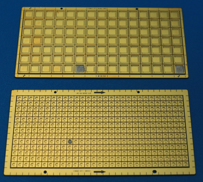
Ceramic-base MCPCB used for ultraviolet phototherapy, an example of material selection driven by specialty medical requirements.
Why MCPCB and MPCB Get Confused in Electrical Sourcing
In the PCB industry, MCPCB means a circuit board whose base layer is a thermally conductive metal — usually aluminum, sometimes copper or ceramic. The metal base spreads heat from LEDs and power semiconductors to a heatsink or enclosure. In low-voltage electrical engineering, MPCB means a motor protection circuit breaker — a switching and protection device that guards motors against overload and short circuit.
The overlap gets worse because some PCB manufacturers use “MPCB” as a short form for metal-base PCB in product naming. WODE Circuit Technology (Zhuhai) Co., Ltd., for example, lists a “Double sided MPCB” product that is an aluminum-base board for home appliances, not a circuit breaker. The same four letters therefore carry opposite meanings depending on whether the conversation is about boards or switchgear.
Two specification systems, one set of confused search terms
| Sourcing dimension | MCPCB (Metal Core PCB) | MPCB (Motor Protection Circuit Breaker) |
|---|---|---|
| What it is | Metal-base circuit board for power electronics | Low-voltage switching/protection device for motors |
| Typical pole or layer structure | Single-sided or double-sided circuit layers | 1P / 2P / 3P / 4P pole versions |
| Key selection parameter | Base material thermal conductivity, copper thickness, dielectric | Trip curve: B (3–5×In), C (5–10×In), D (10–20×In) |
| Supply type context | AC/DC circuits mounted on the board | AC MPCB, DC MPCB, Solar DC MPCB (600–1500 V DC) |
| Typical project context | LED drivers, power supplies, motor light boards, medical device electronics | Household distribution box, industrial motor circuit, EV charger infrastructure |
| Feature variants | Thermoelectric separated, ceramic base, high-voltage aluminum, coverlay | RCBO combined, high breaking capacity, indicator type, CE marking, IP40 protection, flame-retardant enclosure |
When a buyer searches for “MPCB,” describing the intended installation — a printed board versus a panel-mounted breaker — removes the ambiguity faster than any part number. The IEC 60947-4-1:2023 standard, which specifies requirements for motor protective switching devices, is the relevant reference for the breaker side, while MCPCB selection follows the thermal and electrical requirements of the circuit itself.
Project Conditions That Drive MCPCB Selection
MCPCB selection cannot be a one-page checklist because operating conditions change the correct answer. Indoor lighting typically stays in 0°C to +40°C with 30% to 80% humidity and no special corrosion exposure. Outdoor lighting faces –40°C to +50°C, high humidity, salt spray, UV radiation and wind-driven rain. Automotive lighting sits in an engine compartment that can range from –40°C to +125°C, with vibration, oil contamination and moisture condensation. Industrial control applications add high dust, oil mist, corrosive gases and electromagnetic interference.
These conditions matter because the metal base, the laminate system, the copper weight, the solder mask and the final finish all affect how a board survives in a specific enclosure. A board that works in a residential luminaire may fail in an outdoor streetlight or an industrial cabinet.
MCPCB Base Materials Seen in Production
WODE Circuit Technology (Zhuhai) Co., Ltd., a PCB and FPC manufacturer founded in 2003 in Zhuhai, China, offers a useful view of how base material choices are applied to different projects. The company operates a 150,000 m² plant with more than 500 employees and annual output of 6,000,000 sqm, and holds ISO9001, ISO14001 and IATF16949 certifications while producing to UL, RoHS and REACH requirements. Its MCPCB examples show how design teams translate environment into board construction.
| Base material / design | Example product | Construction highlights | Project fit |
|---|---|---|---|
| Al1060 | MCPCB for Road Lighting | Single-sided, 1 oz copper, 1.6 mm ±10%, HASL-LF, white solder mask / black silkscreen | Outdoor and road lighting where thermal spreading and corrosion resistance matter |
| Al5052 | MCPCB for Motor Lighting | Single-sided, 1 oz, 1.6 mm ±10%, matt black solder mask, HASL | Motorcycle and vehicle lighting with vibration and wide temperature swings |
| Al1 | High Voltage MCPCB | Single-sided, 1 oz, 1.6 mm ±10%, OSP | Lighting requiring higher electrical clearance |
| Al5 | Double sided MPCB | 70/70 µm copper, 1.6 mm ±0.16, white/white solder mask, black/black silkscreen, HASL-LF | Home appliance boards needing double-sided routing plus metal-base cooling |
| Cu base | Thermoelectric Separated Cu based PCB | 35 µm copper, 1.6 mm ±0.16, OSP, separated thermal and electrical paths | High-power lighting where heat path and circuit path are separated |
| Ceramic | Ceramic based PCB | Designed for ultraviolet phototherapy | Specialty medical and optical modules needing high thermal and electrical isolation |
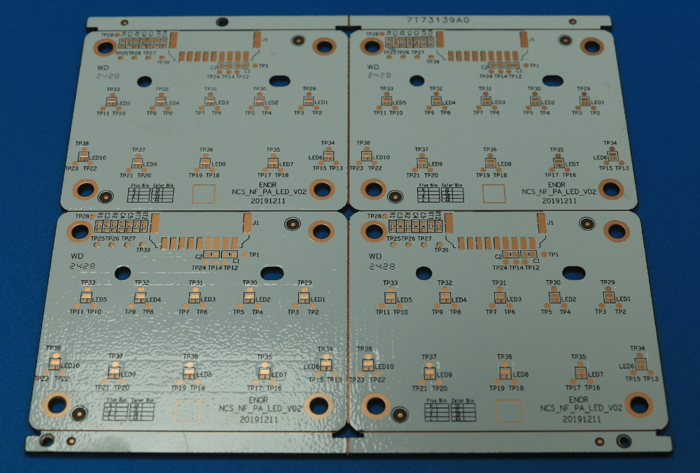
Thermoelectric separated double-sided copper-base PCB. Keeping the heat conduction path separate from the electrical path matters when power density is high.
Technical Explanation: What the Specs Actually Mean
Base material. Aluminum is the most common MCPCB base because it balances thermal performance, weight and cost. Al1060 and Al5052 appear in different lighting boards; copper-base boards are used when maximum heat spreading is needed; ceramic-base boards provide high electrical isolation and are specified for specialty applications such as ultraviolet phototherapy.
Copper foil thickness. Standard lighting boards commonly use 1 oz copper. Double-sided aluminum-base boards for home appliances use 70/70 µm copper, while thermoelectric separated copper-base boards use 35 µm copper. Copper thickness determines current-carrying capacity and affects thermal spreading across the circuit layer.
Overall thickness and tolerance. A common finished thickness is 1.6 mm, specified as ±10% or ±0.16 mm depending on the product. Panel sizes are optimized for production efficiency — examples include 208.00 × 225.00 mm, 243.00 × 243.00 mm, 217.54 × 197.80 mm and 133.80 × 120.00 mm.
Solder mask and silkscreen. White solder mask is typical for LED lighting to reflect light; matt black solder mask appears on motorcycle light boards where appearance and glare control matter; green solder mask is common on general-purpose boards. Silkscreen color is chosen for legibility and branding.
Surface finish. HASL-LF is widely used for solderability and cost. OSP provides a flat surface for component mounting. ENIG and other finishes are available for higher-reliability or wire-bonding requirements. The finish should be matched to the assembly process and target environment.
Coverlay and special constructions. Coverlay aluminum boards use a white coverlay instead of conventional solder mask, which suits certain LED module designs. Thermoelectric separated copper-base boards create independent physical paths for heat and electricity, reducing thermal interference in high-drive-current circuits.
Application / Use Cases: Matching Board Type to Project
Industrial controls
Product 5517, a single-sided CEM-1/CEM-3/FR-4 board with aluminum option, covers PLC main control boards and I/O modules, DCS field stations, motion control cards, industrial HMI motherboards, robot controllers, IIoT smart sensor nodes and power automation equipment. It is designed for –20°C to +70°C, with an extended range of –40°C to +85°C for harsh environments. The board is expected to tolerate high dust, humidity, oil contamination, corrosive gases such as H₂S and SO₂, and strong electromagnetic interference from VFDs and welders.
Medical electronics
In life support and monitoring systems, medical imaging equipment, in-vitro diagnostic devices and implantable electronics, the board must survive high-temperature steam sterilization at 134°C/30 psi and chemical disinfectants. Special requirements include ISO 13485, IEC 60601-1 with leakage current below 10 µA, ISO 10993 biocompatibility, IEC 61000-4 EMC tests and IP67/IP68 protection. High-precision biosignal acquisition at nV-level amplification adds further demands on material stability.
Automotive electronics
Powertrain control units, chassis and safety systems, and ADAS domain controllers operate in engine-compartment conditions from –40°C to +125°C, with transient peaks at +150°C. AEC-Q100 qualification and ISO 26262 functional safety up to ASIL-D set the quality bar. WODE’s IATF16949 certification aligns with automotive supply-chain expectations.
Lighting and home appliances
Road lighting boards use Al1060 aluminum with single-sided construction, 1 oz copper, 1.6 mm thickness and HASL-LF finish. Motorcycle light boards use Al5052 aluminum with matt black solder mask for vibration and wide-temperature environments. Coverlay aluminum boards support LED modules requiring selective coverage. Double-sided aluminum-base boards serve home appliances that need routing on both sides plus metal-core cooling. Small appliance lighting motherboards, by contrast, use FR-4 double-sided construction at 1.0 mm thickness with HASL-LF — a reminder that not every lighting-related board needs a metal base.
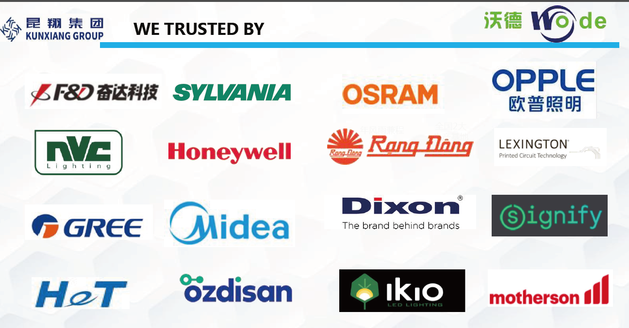
Customer reference evidence: WODE has been qualified by global brands including Signify, Osram, Opple and NVC.
Case records show WODE has been qualified by global brands including Signify, Osram, Opple and NVC. A German lighting OEM project used 5,000 sqm of boards over five years with stable operation under harsh European climate conditions and German safety requirements. For order planning, mass orders start at 100 sqm, while sample quantity is unlimited.
Market Trend Analysis
Verified market data points to sustained investment in exactly the equipment categories where MCPCB thermal management matters. According to Grand View Research, the global molded case circuit breaker market was valued at USD 6.23 billion in 2023 and is projected to reach USD 15.52 billion by 2030, with residential end-use growing at a CAGR of 14.3%. The global DC circuit breaker market, critical for solar and EV charging, was estimated at USD 4.13 billion in 2023 and is expected to grow at a CAGR of 8.7% until 2030. Fortune Business Insights reports that Asia Pacific dominated the circuit breaker industry with a 40.23% revenue share in 2025, driven by grid modernization in China and India.
These figures describe switchgear, not PCBs, but they indicate where power-electronics projects are heading: residential distribution, rooftop solar, EV charging infrastructure and grid-modernization programs. Solar DC circuit breakers, for example, are required to handle system voltages of 600V, 1000V or 1500V DC. Every one of those systems contains control boards, driver boards or power supply boards that generate heat. For specifiers, the implication is that MCPCB selection is becoming part of thermal design rather than a late-stage purchasing step.
Comparison with Traditional Solutions
The traditional alternative to MCPCB is standard FR-4. FR-4 is mature, cost-effective, available in multilayer constructions, and well suited to dense signal routing. Its limitation is low thermal conductivity: heat from power components must be removed by added heatsinks, thermal vias or active cooling.
MCPCB solves the heat-spreading problem through a metal base layer, which is why it dominates LED lighting and power modules. But the comparison has a real boundary. A single-sided aluminum-base board offers limited routing area and is not the right choice for high-density digital circuits that require many signal layers, BGA fan-out or controlled impedance. In those cases, multilayer FR-4 is the technically reasonable solution, sometimes combined with metal-base sections or dedicated heatsinks. Ceramic-base boards offer excellent electrical isolation and high-temperature capability but cost more and are more brittle in mechanical handling than aluminum-base boards. Copper-base boards provide the highest thermal performance but carry higher material cost. The correct answer is project-dependent, not material-dependent.
Future Outlook
Higher power density in lighting, solar, EV charging and energy storage will continue to push MCPCB designs toward better thermal paths. Thermoelectric separation, double-sided aluminum base, copper base and ceramic base will each find a clearer role as project requirements sharpen. Buyers will increasingly need to define operating environment, certification targets and design-for-manufacturing constraints before ordering, rather than treating the board as a commodity. At the same time, terminology discipline will become more important: distinguishing MCPCB from MPCB in specifications and purchase orders prevents costly misunderstandings between the PCB design team and the low-voltage equipment team.
Frequently Asked Questions
1. What is the difference between MCPCB and MPCB?
MCPCB stands for Metal Core Printed Circuit Board, a thermally conductive circuit board base. MPCB in low-voltage electrical engineering typically stands for Motor Protection Circuit Breaker, a device that protects motors against overload and short circuit. IEC 60947-4-1:2023 specifies requirements for motor protective switching devices. Confusion increases because some PCB manufacturers, including WODE, use “MPCB” in product naming to mean metal-base PCB, such as the Double sided MPCB for home appliances. Confirming whether the project requires a board or a breaker is the first step.
2. Which MCPCB base material should be used for outdoor lighting?
Outdoor lighting examples in production include road lighting boards made with Al1060 aluminum base, single-sided construction, 1 oz copper, 1.6 mm overall thickness ±10%, white solder mask and HASL-LF finish. Outdoor environments typically include –40°C to +50°C, high humidity, salt spray and UV exposure; the aluminum base spreads heat while the surface finish and solder mask resist corrosion.
3. Can MCPCB be used in industrial control and automotive electronics?
Yes. In industrial controls, a single-sided CEM-1/CEM-3/FR-4 board with aluminum option (product 5517) is suitable for PLC I/O modules, DCS field stations, motion control cards, HMI motherboards, robot controllers, IIoT nodes and power automation equipment. It is designed for –20°C to +70°C, with an extended range of –40°C to +85°C, and withstands high dust, humidity, oil, corrosive gases and EMI. In automotive electronics, boards for powertrain control, chassis and safety systems, and ADAS operate at –40°C to +125°C, with transient +150°C, and must satisfy AEC-Q100 and ISO 26262 up to ASIL-D requirements.
4. What certification and compliance requirements apply to MCPCB in medical projects?
Medical electronics projects typically require ISO 13485, IEC 60601-1 with leakage current below 10 µA, ISO 10993 biocompatibility, IEC 61000-4 EMC tests and IP67/IP68 protection. Boards may also need to survive high-temperature steam sterilization at 134°C/30 psi. WODE’s product 5517 is positioned for these medical requirements, and the company holds ISO9001, ISO14001 and IATF16949 while producing to UL, RoHS and REACH standards.
5. What should a buyer verify before ordering custom MCPCB?
For OEM/ODM orders, typical customization points are laminate material, PCB thickness, surface treatment, solder mask color and logo printing. WODE’s production capability includes monthly capacity of 600k sqm, lead time of 7–15 days, MOQ of 80 sqm and 100% electrical test. Mass orders start at 100 sqm, while sample quantity is unlimited. Buyers should also confirm operating temperature, certification target, and whether double-sided routing or thermoelectric separation is required for the specific project.
For a complete overview of WODE’s product lines and manufacturing capability, the company brochure is available for download: WODE company brochure (PDF)
Have Questions or Need More Details?
Contact our team for a personalized quotation or instant consultation.
Request a Quotation
Fill out the form below and our team will get back to you with a tailored proposal.
WhatsApp Direct Chat
Prefer to chat in real-time? Message us on WhatsApp for instant assistance & quick answers.
- Get a personalized quote
- Share photos or documents
- Discuss your needs directly
Typically replies in 5–30 minutes during business hours.