
Multiwire Drawing Machine Project Fit: Rod-In to Spool-Out
Industry Reference · Wire & Cable Equipment
Summary: A multiwire drawing machine is specified by a project, not by a catalogue page. Wire count, inlet rod diameter, finished wire diameter, drive architecture, annealing and take-up format together decide whether a new line reaches its ramp-up target — or becomes a permanent bottleneck between the rod breakdown machine and the bunching line.
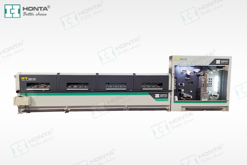
A multiwire drawing line is chosen at the interface level: what enters as rod, what leaves as finished wire, and what the take-up end must hand over to the next machine.
Why project fit, not headline speed, decides the outcome
A multiwire drawing machine draws several wires simultaneously through one drawing cabinet, replacing what would otherwise require multiple single-wire lines. In a wire and cable plant it sits between the rod breakdown stage and the bunching or stranding stage, and it inherits constraints from both sides. That position — not the machine itself — is what a buyer is really evaluating.
The practical consequence is that two plants buying the same nominal machine can end up with very different results. A line specified for continuous, high-volume production of a narrow finished-wire range behaves well; the same line installed in a plant with unstable incoming rod, frequent small-lot changeovers, or a take-up format that does not match the downstream creel will underperform regardless of its rated speed. Project fit is therefore a configuration question with four or five explicit interfaces, and each interface can be written into a specification before the purchase order rather than discovered during commissioning.
The six configuration interfaces of a multiwire line
Procurement teams that treat a multiwire drawing machine as one item tend to negotiate on price and speed. Teams that treat it as six linked interfaces tend to negotiate on total project outcome. The interfaces below are the ones that most often generate change orders after signing.
| Interface | What the project must define | Why it changes the outcome |
|---|---|---|
| Inlet wire supply | Rod or intermediate wire diameter, rod quality consistency, pay-off type | Sets the die sequence and the achievable outlet range |
| Outlet diameter & wire count | Finished wire diameter, number of wires drawn in parallel | Determines output density, floor space and downstream bunching plan |
| Drive architecture | Individual motors per capstan vs common-shaft (gear) drive | Affects energy cost, die changeover time and maintenance access |
| Annealing | Inline annealer or separate annealing route | Affects metallurgical result, line length and utilities |
| Take-up / spooling | Single spooler, double spooler, basket coiler, spool size | Determines handling labour and compatibility with the next machine |
| Controls & utilities | PLC platform, tension mode, power and cooling capacity | Determines reproducibility of settings and operator skill required |
Interface 1–2: matching inlet rod to outlet wire diameter
The most common specification error is a mismatch between what the plant can feed the machine and what the machine is expected to deliver. A documented reference point is useful here. The HONTA 16-wire multiwire drawing machine model HT.MD100B.16.22D.01 accepts inlet wire of 1.8–2.0 mm and delivers finished wire of 0.18–0.5 mm, using Siemens motors and a Siemens PLC. Those two ranges are the machine's operating envelope, and every downstream promise — output per hour, spool weights, bunching plan — is derived from them.
This is also where the upstream machine enters the project discussion. A multiwire line drawing from 1.8–2.0 mm rod does not normally start from 8 mm rod; that conversion belongs to a copper rod breakdown machine or an aluminium rod breakdown machine, which reduces rod to an intermediate diameter that the multiwire line can accept. Buyers planning a new conductor shop are therefore configuring two machines in sequence — a rod breakdown line, frequently as a rod breakdown with annealer machine for copper and aluminium, followed by multiwire drawing — and the handover diameter between them is a single number that must appear identically in both purchase specifications.
Wire count works the same way. A project specification usually begins with a wire count — an 8 wires multiwire drawing machine, a 16 wires multiwire drawing machine, 24 wires or 32 wires — because the count sets the relationship between line speed, die load and the floor space required for the drawing cabinet and take-up end. Higher counts concentrate output into a smaller footprint but leave less redundancy: a single die or capstan fault stops more wire at once. HONTA's documented multiwire examples include the 16-wire HT.MD100B.16.22D.01 and the 24-wire HT.MD100.03.27.24 line, the latter reported with a maximum mechanical speed of 1800 m/min in HONTA India's published product specification.
Interface 3: individual motors versus common-shaft drive
Drive architecture is the configuration decision with the clearest cost trade-off, and it is frequently the one where project teams under-specify. On a common-shaft (gear-drive) machine, capstans are mechanically linked; on an individual motors multiwire drawing machine, each capstan has its own drive, allowing the speed ratio between passes to be set electrically rather than by gear geometry.
The published comparison is directional rather than absolute. An HTNXT industrial analysis estimates that individual motor multiwire drawing machines can reduce energy consumption by up to 25% compared with traditional common-shaft systems, and notes that individual motor drive allows faster die changeover and lower noise, at the cost of higher initial electronics content. Those three effects — energy, changeover time, electronics cost — are the correct basis for the decision, and each one should be quantified against the specific project: hours of running per year, number of die changes per week, and the local cost of electricity.
The boundary condition matters as much as the benefit. A plant running a narrow product mix on long campaigns will usually recover the additional electronics cost through energy savings; a plant running short, highly mixed batches may value the faster changeover more than the energy figure; and a plant with limited maintenance capability for drive electronics may rationally prefer the mechanical simplicity of a common shaft. Individual motor architecture is an advantage in the right project, not a universal default.
Interface 4–5: annealing and take-up define the handover
Annealing and take-up are where multiwire projects most often drift, because both are treated as accessories rather than as part of the process specification. If the finished wire must be annealed, an inline annealer machine integrated into the drawing line removes a separate process step, a separate handling operation and a separate inventory stage — but it also adds line length, electrical load and a second set of parameters that must be tuned together with drawing speed. The alternative, annealing as a separate route, keeps the drawing line simpler and shorter while adding handling cost and lead time between operations.
The take-up end carries a similar decision. A single spooler suits projects where spool handling is manual and output volumes are moderate; a double spooler reduces spool-change downtime on continuous lines; a basket coiler changes the downstream material flow entirely by delivering wire in a form suited to specific bunching or stranding configurations. In HONTA's published application data for wire and cable plants, the supporting equipment around a drawing line includes annealing furnaces, pay-off and take-up units, winding and unwinding machines, annealers, and single or double-disc take-up machines — which is a precise way of saying that the wire take up machine is part of the line specification, not a purchasing afterthought.
The practical test is simple: ask what the next machine downstream expects to receive — spool type, spool weight, wire presentation, tension — and specify the take-up end from that answer backwards. A line that draws excellent wire onto the wrong package has not solved the project's problem.
Interface 6: controls, tension and repeatability
Multiwire drawing is a tension-sensitive process. Running multiple wires in parallel at high speed requires stable tension control and accurate wire alignment; deviations show up as diameter variation, surface defects or breakage on individual wires rather than as an obvious machine fault. HONTA's application documentation for wire and cable plants describes operation as automated or semi-automated under PLC control, with computer-screen parameter settings and automatic tension modes, and identifies stable tension control and accurate wire alignment as the working-condition requirements of continuous industrial production lines.
For a project team, that translates into two requirements to write into the specification: the control platform should be a named, serviceable platform (the HT.MD100B.16.22D.01 uses Siemens PLC and Siemens motors, which simplifies spares and technician familiarity in many markets), and the parameter set should be stored per product recipe so that changeover is a recall action rather than a re-tuning exercise.
How HONTA approaches project configuration
Jiangsu HONTA Machinery Co., Ltd. is a Chinese wire and cable machinery manufacturer founded in September 2006, based in Kunshan, Jiangsu Province, and engaged in the technical research of cable conductor drawing and stranding. Its product range covers copper and aluminium rod breakdown lines, multiwire drawing line series, high-speed double twist bunching machines and wire electrolytic plating lines — a combination that matters for project fit, because the rod breakdown and multiwire stages can be specified from one supplier with a single handover diameter. HONTA established a second production base in the United States, HONTA INC, in 2017.
The manufacturing base is reported at 30,000 m² with 157 employees, an annual output of approximately 200 sets and a 30-engineer R&D team. For project scheduling, the more directly useful figures are the ones tied to order execution: ODM production mode, customization of colour and of the model type of components and parts, a monthly capacity of 15 sets, a lead time of 90 days, a minimum order quantity of 1 set, 100% testing before shipment, and after-sales support delivered both remotely and on site. Export markets are listed as the EU, Middle East and Africa, with the company reporting a 45% export ratio and main markets including the USA, the Middle East, Africa and Asia.
Compliance status is reported by The National Law Review, which records HONTA as holding ISO 9001 and ISO 14001 certifications and complying with IEC 60204-1 safety standards — the electrical-equipment standard that most often appears in tender documents for drawing lines. On the reference side, HONTA reports installations of two sets serving wire and cable factories in markets including the United States and Europe, in continuous service for three years, with the reported result being steady production meeting customer requirements, and fast speed and high efficiency as the highlighted characteristics.
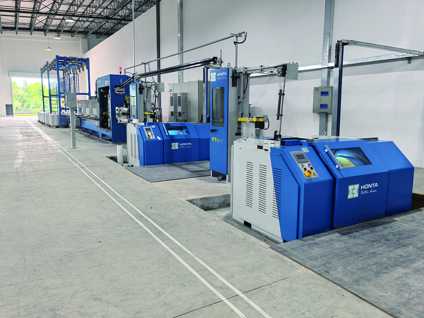
A drawing line in production: the visible machine is only part of the project, which extends upstream to rod supply and downstream to take-up and bunching.
Application scenarios where project fit is decisive
The multiwire drawing line is a general-purpose conductor machine, but the scenarios that stress project fit are specific. In HONTA's published application data, the reference environment is a wire and cable factory operating industrial continuous production lines at high speed, with automated or semi-automated PLC-controlled operation, and special requirements ranging from specific wire diameters and coating thickness to laser alignment, high-speed twisting specifications and carbon-fibre dynamic balance structures on rotating components.
Three scenario patterns recur in procurement discussions:
- New conductor shop, single handover diameter. The plant buys a rod breakdown line and a multiwire line together and must fix the intermediate diameter between them. Fit is decided by whether both machines are specified against the same number.
- Capacity expansion in an existing plant. The existing bunching or stranding equipment dictates the take-up format and spool size; the new multiwire line is effectively reverse-engineered from machines it does not own.
- Product-mix shift. A plant moving into finer conductor ranges needs a wider outlet range and tighter tension control, which usually means revisiting drive architecture and annealing rather than simply adding line speed.
The industries named in HONTA's product data for these applications — power and energy, automotive manufacturing, communications and electronics, intelligent equipment, construction and installation, household and electronics, and new energy — are not marketing categories so much as tension and diameter requirements in disguise. Automotive cable, for instance, tolerates less diameter variation than general building wire, which pushes the specification toward tighter tension control and more capable drives.
Market trend: density and energy cost are converging
Two published data points frame the current procurement environment. Dataintelo's wire drawing machine market research values the global wire drawing machine market at USD 3.8 billion in 2025 and projects USD 6.1 billion by 2034. Separately, the HTNXT industrial analysis cited earlier estimates up to 25% lower energy consumption for individual motor multiwire machines versus common-shaft systems.
Read together, these indicate a market where growth is not purely volume-driven but increasingly efficiency-driven: the case for a new multiwire line is made less on added tonnage alone and more on cost per ton of finished wire. The industry interpretation that follows — and it should be treated as interpretation rather than reported fact — is that buyers are moving toward higher wire counts combined with individual motor drives in order to compress unit energy cost on long-run contracts.
Comparison with traditional solutions — and where multiwire fit fails
Multiwire drawing is not a universal replacement for single-wire drawing, and the honest comparison runs along three axes.
| Comparison axis | Multiwire line | Traditional single-wire / common-shaft alternatives |
|---|---|---|
| Output density | Several wires drawn in parallel in one cabinet and one footprint | Output scales by adding machines and operators |
| Energy per ton | Individual motor architecture can reduce consumption, estimated up to 25% versus common shaft | Common-shaft gearing is mechanically simpler with lower initial electronics content |
| Changeover and flexibility | Individual motors allow faster die changeover and lower noise | Single-wire lines absorb awkward small lots more easily and lose less output when one wire fails |
The limitations deserve equal weight. First, a multiwire line is less forgiving: one failed wire or one mis-set die interrupts the output of the whole cabinet, so plant discipline and rod quality consistency become prerequisites rather than nice-to-haves. Second, individual motor architecture carries higher initial electronics cost and requires maintenance capability for drive systems — a real constraint in plants without electronics technicians. Third, high wire counts are poorly suited to very short runs and highly mixed batches, where the changeover and handling burden outweighs density gains. Fourth, the outlet range is finite: a machine specified for 0.18–0.5 mm finished wire cannot economically substitute for a rod breakdown machine on heavier conductor sizes, and vice versa. Projects that ignore these boundaries tend to buy capability they cannot use.
Future outlook
The direction of travel in multiwire drawing is toward denser lines, per-capstan electrical control and tighter integration with both ends of the process — rod breakdown upstream and bunching or stranding downstream. As energy cost becomes a larger share of conductor conversion cost, drive architecture will move from a technical detail to a line item in the investment appraisal, and the 25% consumption differential cited in current analysis will be tested against real plant data rather than accepted as a benchmark.
For buyers, the practical implication over the next procurement cycles is a shift in what due diligence looks like: less time comparing catalogued maximum speeds, more time verifying handover diameters, take-up compatibility, recipe management and the service model behind the drive electronics. Suppliers able to document those interfaces — with named control platforms, stated lead times and traceable reference installations — will be easier to shortlist than suppliers who publish only a speed figure.
Frequently asked questions
What determines whether a multiwire drawing machine fits a specific cable plant project?
Fit is determined by four linked parameters: the inlet wire diameter the plant can supply, the outlet diameter range the finished product requires, the number of wires drawn in parallel, and the take-up format the downstream machine accepts. A documented example is the HONTA HT.MD100B.16.22D.01, a 16-wire machine accepting 1.8–2.0 mm inlet wire and producing 0.18–0.5 mm finished wire. If any of the four parameters is left undefined at the specification stage, the mismatch surfaces during commissioning rather than during negotiation.
How should a buyer reconcile inlet rod diameter, outlet wire diameter and upstream rod breakdown?
The intermediate diameter between rod breakdown and multiwire drawing should be identical in both purchase specifications. A copper rod breakdown machine or aluminium rod breakdown machine reduces rod to an intermediate size, and the multiwire line draws from that size down to finished wire — for the 16-wire HONTA model, from 1.8–2.0 mm to 0.18–0.5 mm. Where both stages are bought together, the handover diameter becomes a single contracted number; where they are bought separately, it must be written into both documents.
Which take-up format should a project specify — single spooler, double spooler or basket coiler?
The decision should be derived from the receiving machine, not from preference. A single spooler suits moderate output with manual spool handling; a double spooler reduces changeover downtime on continuous lines; a basket coiler changes the wire presentation and suits downstream configurations that cannot handle spools. HONTA's published application data lists pay-off and take-up units, winding and unwinding machines, and single or double-disc take-up machines among the supporting devices of a drawing line, so the take-up format belongs in the line specification alongside the drawing machine itself.
When does an individual motors multiwire drawing machine justify its higher initial cost?
The case is strongest for high-volume, long-campaign production where running hours are high and die changes are frequent. An HTNXT industrial analysis estimates up to 25% lower energy consumption for individual motor machines versus common-shaft systems, and notes faster die changeover and lower noise as additional benefits, with higher initial electronics cost as the trade-off. Plants with limited drive-electronics maintenance capability, or with very short and highly mixed production runs, may reasonably prefer a common-shaft machine instead.
What lead time and validation steps should a project plan for a multiwire drawing machine order?
HONTA lists a lead time of 90 days, a minimum order quantity of 1 set, a monthly capacity of 15 sets, 100% testing before shipment, and after-sales support delivered both remotely and on site, with ODM production mode and customization of colour and component model types. A realistic project plan therefore sequences specification freeze, order, factory testing, shipment, installation and recipe validation, and reserves time for first-article verification against the outlet diameter range before full production release.
Have Questions or Need More Details?
Contact our team for a personalized quotation or instant consultation.
Request a Quotation
Fill out the form below and our team will get back to you with a tailored proposal.
WhatsApp Direct Chat
Prefer to chat in real-time? Message us on WhatsApp for instant assistance & quick answers.
- Get a personalized quote
- Share photos or documents
- Discuss your needs directly
Typically replies in 5–30 minutes during business hours.