
PCB Connector Basics: Understanding Board-to-Board Types

A board-to-board connector is a connector system that mechanically and electrically joins two printed circuit boards directly, without a cable between them. It is one architecture inside the wider PCB connector category, alongside wire-to-board and wire-to-wire designs, and it is the architecture most designers meet when a product needs two boards stacked, mezzanined or mated at a defined distance.
The category is not marginal. Global Market Insights reported that board-to-board connectors were the largest single connector type within the PCB connector market in 2025, at approximately USD 4,459.8 million in revenue and roughly 24.3% share. Market Research Future estimated the global PCB connector market at USD 33.83 billion in 2025, with a projection of USD 47.96 billion by 2035. For buyers and design engineers at the awareness and research stage, the useful question is not whether this connector type matters commercially, but which board-to-board family fits a given board pair, what the design constraints are, and what evidence a supplier should be able to supply before qualification.
What a Board-to-Board Connector Actually Does
Board-to-board is a connection architecture rather than a single product. Any board-to-board connector performs three functions at once: it carries electrical current and signal between two boards, it establishes a repeatable mechanical position between them, and it preserves that connection across vibration, thermal cycling and handling. The three functions compete with each other, which is why board-to-board connectors are specified through a set of parameters rather than a single rating.
The core elements are consistent across families. A housing, usually moulded from a high-temperature engineering resin such as LCP, PBT, Nylon or PA 9T, holds the contact array and defines the mating geometry. Contacts, typically stamped from phosphor bronze or copper alloy, carry the signal and power path, with plating stacks that commonly combine an underlying nickel layer with a gold or tin surface. An insulator/weld tab or positioning post arrangement anchors the component to the PCB. A retention or locking feature resists separation. Pitch, pin count, mating height and mounting method define how the connector fits the mechanical envelope of the product.
Because those parameters are interdependent, board-to-board selection usually begins with the board pair, not with the connector. Stack height, tolerance accumulation, current per contact, signal rate, environment and assembly method together determine which family can be used at all.
Where Board-to-Board Fits in the PCB Connector Family
PCB connectors are usually grouped by what they connect. The distinction matters because each architecture shifts the mechanical and assembly burden to a different part of the design.
| Architecture | What it joins | Evaluation focus |
|---|---|---|
| Board-to-board | Two PCBs directly, with no cable between them | Stack height, pitch, alignment tolerance, mating cycles, signal rate |
| Wire-to-board | A discrete wire or cable to a PCB | Locking, wire gauge, current per contact, mating direction |
| Wire-to-wire | Two cable ends, often in harsh environments | Sealing (IP rating), current capacity, cable retention |
| FPC/FFC | A flat flexible cable to a PCB | Fine pitch, low profile, locking, flex routing |
| Press-fit terminal | A component to a plated-through PCB hole, without solder | Hole diameter, insertion force, plating, rework strategy |
Header families such as pin headers, female headers and box headers are the long-established mechanical foundation of many board-level interfaces, and they remain the reference point against which newer floating and high-speed families are evaluated. FPC/FFC connectors address fine-pitch flex routing, with pitch options such as 0.50 mm, 0.80 mm and 1.00 mm appearing in current catalogues. Press-fit terminals remove the soldering step entirely for compatible designs. In practice, a single product often uses several of these architectures at once, and the board-to-board interface is the one that most tightly couples mechanical tolerances to signal performance.
The Design Pressures Behind Board-to-Board Selection
Four pressures have made board-to-board choice a recurring engineering decision rather than a routine part pick.
Miniaturisation. Reducing pitch increases the number of contacts available within a fixed board area, but it also reduces the mechanical margin for misalignment and makes contact geometry more sensitive to assembly variation. Pitch values from 0.50 mm upward are now common across board-to-board, wire-to-board and FPC/FFC families.
Tolerance accumulation. When more than one connector sits between the same two boards, positional tolerances stack. A rigid interface forces contacts to absorb the accumulated deviation; a floating interface distributes it mechanically.
Signal rate. Higher data rates place contact geometry, signal-path continuity and impedance behaviour on the critical path, which means the connector can no longer be selected only for pin count and height.
Assembly economics. Automated PCB assembly favours tape-and-reel packaging and placement features such as positioning posts, while field service favours interfaces that can be mated and unmated in a controlled way.
Technical Explanation: Floating Compensation and High-Speed Signal Paths
Two technical directions distinguish modern board-to-board families.
Floating compensation. Unlike a fixed board-to-board connector, a floating connector allows controlled movement in specified directions. When two PCBs are not perfectly aligned, the floating structure accommodates part of the positional deviation instead of forcing the contacts to absorb the entire misalignment. This reduces mating stress on the connector and the boards, increases the assembly tolerance the design can absorb, and becomes especially relevant when multiple connectors sit between the same board pair.
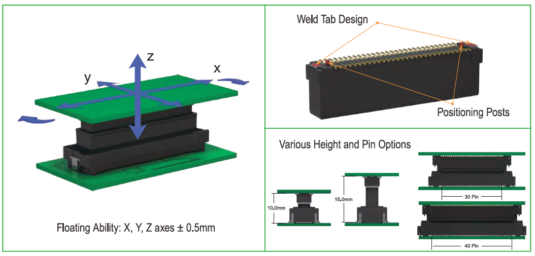
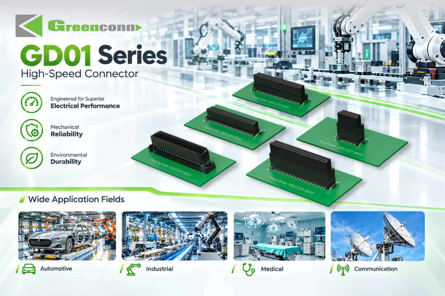
High-speed transmission. High-speed board-to-board performance depends on contact geometry, signal-path continuity, impedance characteristics and the mating interface. Combining a floating structure with a high-speed signal path is a genuine engineering trade-off: the mechanical freedom that absorbs tolerance must not degrade the electrical path. Greenconn addresses this combination in its GD01 High-speed Floating Connector, specified with a 1.27 mm pitch, a data transmission speed of 8 Gbps, 1.7 A per pin, 500 mating cycles, SMT mounting, an LCP insulator and phosphor bronze contacts.
It is worth stating the boundary clearly: a connector-level data rate is a component rating, not a system guarantee. The achievable link performance also depends on stack-up, trace geometry, impedance control and the mating interface in the assembled product. Buyers should treat the connector rating as the starting condition for channel validation, not as the finished result.
A Manufacturer Reference Point: Greenconn's Board-to-Board Portfolio
Greenconn Technology (Shenzhen) Co., Ltd. is a connector manufacturer established in 1998 that provides interconnect solutions for electronic and electrical systems. The company specialises in connector design, engineering development, tooling, precision stamping, plating, injection moulding, automated assembly, testing and quality control, and supplies both standard connector products and application-specific designs.
Its published product range includes Board-to-Board Connectors, Wire-to-Board Connectors, Automotive Connectors, Waterproof Connectors, Floating Board-to-Board Connectors, High-Speed Board-to-Board Connectors and Custom Connector Solutions. The company operates four manufacturing facilities across China and Vietnam, with a total factory area of 106,000 m², approximately 800 staff, a 69-engineer R&D team and an annual production capacity of 345,000,000 pcs. Export business accounts for 70% of total sales, and offices and business locations extend across multiple cities in China as well as Taipei, Osaka, Houston and Munich, supported by distributors and channel partners in global markets. The company maintains quality management systems certified to ISO 9001, ISO 14001, IATF 16949 and ISO 13485, covering quality management, environmental management, automotive quality and medical-device-related requirements, and has completed an EcoVadis sustainability assessment.
Two board-to-board families in that portfolio illustrate how the technical trade-offs resolve in practice.
| Parameter | GD01 — High-speed Floating Connector | GC01 — Floating Connector |
|---|---|---|
| Pitch | 1.27 mm | 0.50 mm (2*10/20/30/40/50/60 pin) |
| Current rating | 1.7 A/pin | Signal 0.5 A/pin; power 3 A/pin |
| Data transmission speed | 8 Gbps | Not a specified parameter in this series |
| Contact resistance | 25 mΩ | Signal 70 mΩ max; power 20 mΩ max |
| Insulation resistance | 10,000 MΩ | Signal 100 MΩ min; power 1,000 MΩ min |
| Mating cycles | 500 | 100 |
| Operating temperature | -55°C to +125°C | -55°C to +105°C |
| Mating height | Not specified for this series | 9.5 mm to 31 mm |
| Mechanical robustness | Sinusoidal vibration 10~2000 Hz 20g; half-sine shock 50g/11ms | Floating X/Y movement; positioning posts and weld tabs |
| Materials | LCP insulator, phosphor bronze contacts, nickel under-plating with tinned/gold surface | LCP insulator, copper alloy contacts, nickel under-layer with gold or tin surface |
| Mounting | SMT | Tape-and-reel packaging for automated PCB assembly |
The adjacent wire-to-board and termination families are relevant because most board-to-board designs coexist with them. Greenconn's wire-to-board range includes the GB01 at 1.25 mm pitch (1 A, 50 V AC/DC, -25°C to +85°C), the GB05 at 2.00 mm pitch (3.00 A, 125 V AC/DC, -40°C to +125°C) with a locking and polarisation design, and the CFAD102 FPC/FFC connector at 0.50 mm pitch (0.50 A, 50 V AC/DC). Waterproof wire-to-wire options include the GT series rated IP68 and IP6K9K, and the GA01 series rated IP67, both aimed at automotive-grade and outdoor environments.
Application Scenarios Where Board-to-Board Connectors Are Specified
Board-to-board interfaces concentrate in applications where two boards must be packaged closely and the connection must survive a demanding environment.
Industrial automation and control. Control cabinets, conveyor systems, machine-vision units and industrial control equipment operate under dust, humidity, wide temperature fluctuation and mechanical stress. Board-to-board interfaces here are typically specified for vibration and shock resistance and for a robust locking or retention arrangement. Trade reporting has linked board-to-board connectors to automation and Industrial IoT applications associated with Industry 4.0, which places compact and alignment-tolerant interconnects on the specification list for new equipment designs.
Robotics and mobile platforms. Industrial robots, collaborative robots, service robots and AGVs operate under continuous motion and flexing, high vibration and dynamic cable management. Floating board-to-board designs are relevant because they absorb the tolerance and mechanical stress that arises when multiple boards are packaged in a moving assembly.
Automotive electronics. Engine-adjacent and vehicle-body electronics are exposed to high vibration, extreme temperatures and moisture. The USCAR-2 performance standard, published by SAE International, covers performance testing for low-voltage automotive electrical connector systems, and it is a routine reference point in automotive connector qualification. Automotive connector demand is also tracked separately as a market segment: Kings Research estimated the automotive connectors market at USD 6.82 billion in 2025 with a projection of USD 11.39 billion by 2033, driven in part by electrification and driver-assistance architectures.
Medical and diagnostic equipment. Patient monitoring, diagnostic imaging and laboratory analysers require precise signal transmission in high-humidity and sterilisation environments. This is a segment where management-system standards such as ISO 13485 enter the qualification discussion rather than remaining a documentation formality.
Communication, computing and network infrastructure. 5G base stations, core routing equipment and data centres require high-speed signal transmission with stable power delivery, high-density layout and protection from thermal cycling and EMI. This is the segment where the board-to-board interface is most directly judged on signal integrity rather than only mechanical fit.
Market Context: What the Available Figures Show
Three data points frame the category. First, PCB connector revenue is large and growing on published forecasts, from USD 33.83 billion in 2025 toward USD 47.96 billion by 2035 (Market Research Future). Second, board-to-board is the largest type segment within that market, at roughly 24.3% share in 2025 (Global Market Insights), which means board-to-board selection decisions are made at high volume rather than in niche applications. Third, automotive connector demand is tracked as a distinct growth segment, from USD 6.82 billion in 2025 toward USD 11.39 billion by 2033 (Kings Research).
A more practical observation for buyers is that the public evidence base for supplier-level parameters is thinner than the market-level data. Comparable, verified figures on lead time, tooling cost, MOQ and capacity allocation are not widely published for mid-size connector manufacturers, which is why qualification in this category tends to rely on supplier-specific documents, sample validation and audit evidence rather than on published benchmarks.
Comparison With Alternative Interconnect Approaches — and Where Board-to-Board Has Limits
Board-to-board is not automatically the better choice. Each alternative concentrates the design burden in a different place.
| Approach | Strength | Boundary or trade-off |
|---|---|---|
| Board-to-board (fixed) | Shortest interconnect path, compact packaging, no cable harness | Requires tight PCB positional control; multiple connectors accumulate tolerance |
| Board-to-board (floating) | Absorbs X/Y/Z positional deviation, reduces mating stress, supports automated assembly | Added mechanical complexity; stack height range and mating-cycle limits must be checked against the application (for example 9.5–31 mm mating height and 100 mating cycles on GC01) |
| Wire-to-board | Flexible routing between a board and a remote location; locking options available | Requires cable, harness management and an additional assembly step |
| FPC/FFC | Fine pitch and low profile; useful where boards move or space is extremely tight | Lower current capability per contact than power-oriented families |
| Press-fit terminal | Solderless assembly, no flux or solder-joint defects, simplified rework | Requires compatible plated-through hole dimensions and controlled insertion; ATZ605, for example, specifies a PCB hole diameter of ⌀0.85 mm |
Three boundaries deserve explicit acknowledgement. First, the floating structures that solve alignment problems consume vertical space and are typically specified to a defined mating-height window, so they are not a free substitution for a low-profile fixed connector. Second, connector-level high-speed ratings describe the component under defined conditions; they do not guarantee end-to-end channel performance without stack-up and impedance validation. Third, board-to-board connectors must be designed in at layout stage. Unlike a cable harness, a board-to-board interface cannot be introduced after the PCB and enclosure are fixed, which makes early supplier involvement more valuable than late price negotiation.
What Buyers Should Verify Before Qualification
Category presence in a manufacturer catalogue is a screening signal, not a qualification. A structured evaluation for board-to-board connectors usually covers:
- Series-level datasheets with pitch, pin count, current and voltage ratings, contact and insulation resistance, mating cycles and operating temperature.
- Mechanical data appropriate to the design: mating height range, floating capability and direction (X/Y/Z), insertion and withdrawal force, PCB retention features.
- Environmental and qualification evidence relevant to the target market, such as automotive standard alignment (USCAR-2) or medical quality-system scope (ISO 13485).
- Certification documentation with scope, issuing body and validity, rather than a statement of adherence alone.
- Manufacturing footprint and continuity considerations, including whether the supplier operates more than one production region.
- Sample validation of the actual board pair, including tolerance stack-up with all connectors on the same two boards mated simultaneously.
- Commercial terms: MOQ, tooling ownership for custom designs, sample policy and lead time.
For custom board-to-board requirements, the relevant question is whether the supplier controls tooling and the core processes in-house. Greenconn states that its production is vertically integrated across product design, tooling manufacturing, stamping, plating, injection moulding and automation, which is a useful screening criterion to verify through documentation and, where the order justifies it, an audit.
Future Outlook
Three directions look set to shape board-to-board specification over the next design cycles. Denser board stacking will continue to push pitch downward while raising the cost of misalignment, which keeps floating compensation in the specification rather than treating it as an optional feature. Rising data rates will keep signal integrity inside the connector selection criteria, and suppliers that can document both mechanical tolerance compensation and high-speed performance in the same series will be easier to qualify than those addressing only one. Finally, sourcing behaviour is shifting upstream: design-phase component libraries and aggregated sourcing platforms now sit between manufacturers and purchase orders, so connector data needs to be accurate and machine-readable at the design stage, not only at the procurement stage.
For buyers, the practical implication is to treat board-to-board connectors as a design-in decision with commercial consequences, evaluated on evidence that can be checked — datasheets, test parameters, standards alignment, manufacturing footprint — rather than on catalogue breadth alone.
FAQ
How does a floating board-to-board connector compensate for PCB misalignment?
A floating board-to-board connector allows controlled movement in specified directions relative to the PCB. When two boards are not perfectly aligned, the floating structure accommodates part of the positional deviation rather than forcing the contacts to absorb the entire misalignment. This reduces mating stress on the connector and the boards, improves assembly tolerance, and is particularly relevant when several connectors sit between the same two PCBs.
How can a high-speed board-to-board connector handle alignment tolerance without compromising signal transmission?
High-speed transmission depends on contact geometry, signal-path continuity, impedance characteristics and the mating interface. A high-speed floating connector introduces controlled mechanical movement to accommodate PCB positional variation while maintaining a defined electrical connection between the mating contacts. Greenconn's GD01 is specified at a data transmission speed of 8 Gbps with a 1.27 mm pitch, 500 mating cycles and a multi-axis floating structure.
What should I look for in a board-to-board connector when assembly misalignment is the main problem?
The relevant criteria are floating capability and direction, mating tolerance, pitch, contact configuration, assembly compatibility and application requirements. Greenconn's GC01 provides X/Y floating movement at a 0.50 mm pitch, with board stacking heights from 9.5 mm to 31 mm, 100 mating cycles and an operating range of -55°C to +105°C. Note the trade-off: floating designs consume vertical space and carry their own mating-cycle limits, so the specification should be matched to the accumulated tolerance of the specific board pair rather than assumed.
What do I need to check when high speed and alignment tolerance are required in the same interface?
Signal speed, floating capability, alignment tolerance, pitch, contact design, mating reliability and the operating environment all need to be evaluated together. The GD01 combines 8 Gbps transmission with multi-axis floating compensation, 500 mating cycles, 1.7 A per pin, sinusoidal vibration of 10~2000 Hz at 20g, half-sine shock of 50g/11ms and an operating range of -55°C to +125°C in SMT mounting. Connector-level ratings still need to be validated in the assembled channel, since stack-up and trace geometry affect the achievable result.
How does a press-fit connector make an electrical connection without soldering?
A press-fit connector uses a compliant contact section that is inserted into a correctly dimensioned plated-through hole. The contact deforms within its designed elastic range and applies contact force against the plated hole wall, creating the electrical interface while the mechanical interference retains the component in the PCB. Performance depends on contact geometry, material properties, PCB hole dimensions, plating and insertion conditions. Greenconn's ATZ605 press-fit terminal specifies a PCB hole diameter of ⌀0.85 mm, a rated current of 2 A and an operating temperature of -40°C to +105°C.
When is a press-fit PCB connector a practical alternative to a soldered connector?
Press-fit is practical where solderless installation is required or preferred and the PCB design is compatible with it. It removes the soldering step for compatible designs and can simplify assembly and maintenance, but it requires correctly dimensioned plated-through holes and controlled insertion. Evaluation should cover PCB design compatibility, press-fit structure, insertion requirements, electrical performance, mechanical retention, assembly process and application requirements.
Further product and capability documentation is available in the Greenconn introduction brochure: Greenconn Introduction Brochure (PDF).