
Pad-Mount Transformer Nameplates, Markings and Grounding
Independent Industry Reference · Distribution Equipment
A North American utility approves a pad-mounted distribution transformer twice — once on electrical performance, and once on what the tank says and how it is bonded. The second approval is where otherwise compliant equipment loses time.
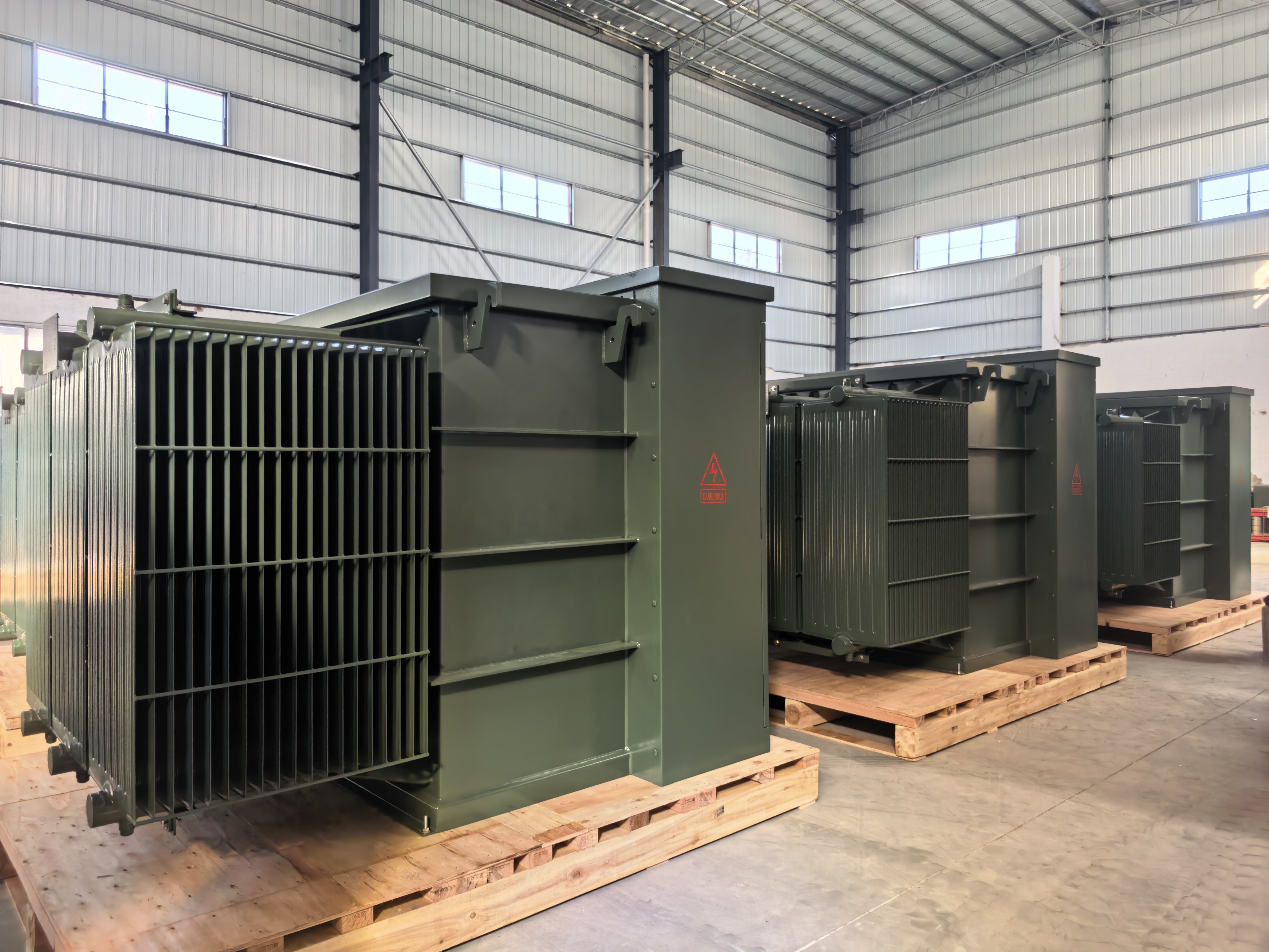
A pad-mounted distribution transformer is a locked, tamper-resistant piece of street equipment. Once the cabinet is closed, everything a utility crew, an inspector or an asset registry will ever know about that unit has to be legible from the outside: the nameplate data set, the warning and connection markings, and the grounding provision that bonds the tank to the system neutral and to earth.
That is why procurement teams evaluating pad mount transformers on kVA, voltage and price alone often meet an avoidable delay at commissioning. A unit can be electrically correct and still be returned to the drawing board because the nameplate does not carry the utility's required data, the tap schedule is presented in an unfamiliar format, the phase labels sit where the crew does not expect them, or the grounding pad will not accept the connector the utility keeps on its trucks.
This reference examines the nameplate, marking and grounding layer of three-phase and single-phase pad-mounted distribution transformers as North American utilities typically specify it, and how those details can be adjusted through ODM engineering when a catalogue configuration does not match a local distribution standard.
At a glance
- Manufacturer:Winley Electric (Xiamen Winley Electric Co., Ltd), founded 2014, headquartered in Xiamen, China, with manufacturing facilities in Shanghai and Guangdong.
- Product scope: three-phase pad-mounted transformers (ZGS), single-phase pad-mounted transformers (DGS) and other liquid-filled and dry-type distribution transformers, exported to more than 60 countries.
- Certification: UL/cUL listing E536138 for three-phase pad-mounted transformers (45–5000 kVA, high voltage up to 36 kV) and single-phase liquid-filled pad-mounted transformers (10–250 kVA); UL E531446 for dry-type units; ISO 9001, ISO 14001 and ISO 45001.
- Customization: OEM/ODM engineering up to 10 MVA and 36 kV; minimum order quantity one unit; typical production lead time 4–8 weeks; monthly capacity 500 units.
- Warranty: 24 months from the bill of lading date, with free replacement of damaged accessories.
Why this layer decides acceptance, not the data sheet
Distribution transformers are approved against utility standards rather than against a generic product description. In North America, the reference point for three-phase pad-mounted, compartmental-type, self-cooled distribution transformers is IEEE C57.12.34-2022, the current edition of the IEEE standard requirements for units rated 10 MVA and smaller. That document defines the transformer type and the identification practice that individual utilities then extend with their own drawing-level requirements.
The consequence for buyers is practical rather than academic. Two utilities in adjacent service territories can order the same 500 kVA unit and demand different nameplate layouts, different tap presentation, different marking sets and different grounding hardware. The electrical design is identical; the acceptance package is not.
Because the pad-mounted enclosure is sealed and locked during normal operation, there is no second chance to communicate this information. The nameplate is the record of what the unit is; the markings are the operating instructions; the grounding provision is the safety interface. All three are reviewed before energization, and all three are typically fixed at the drawing stage rather than at the site.
What a North American utility expects to read on the nameplate
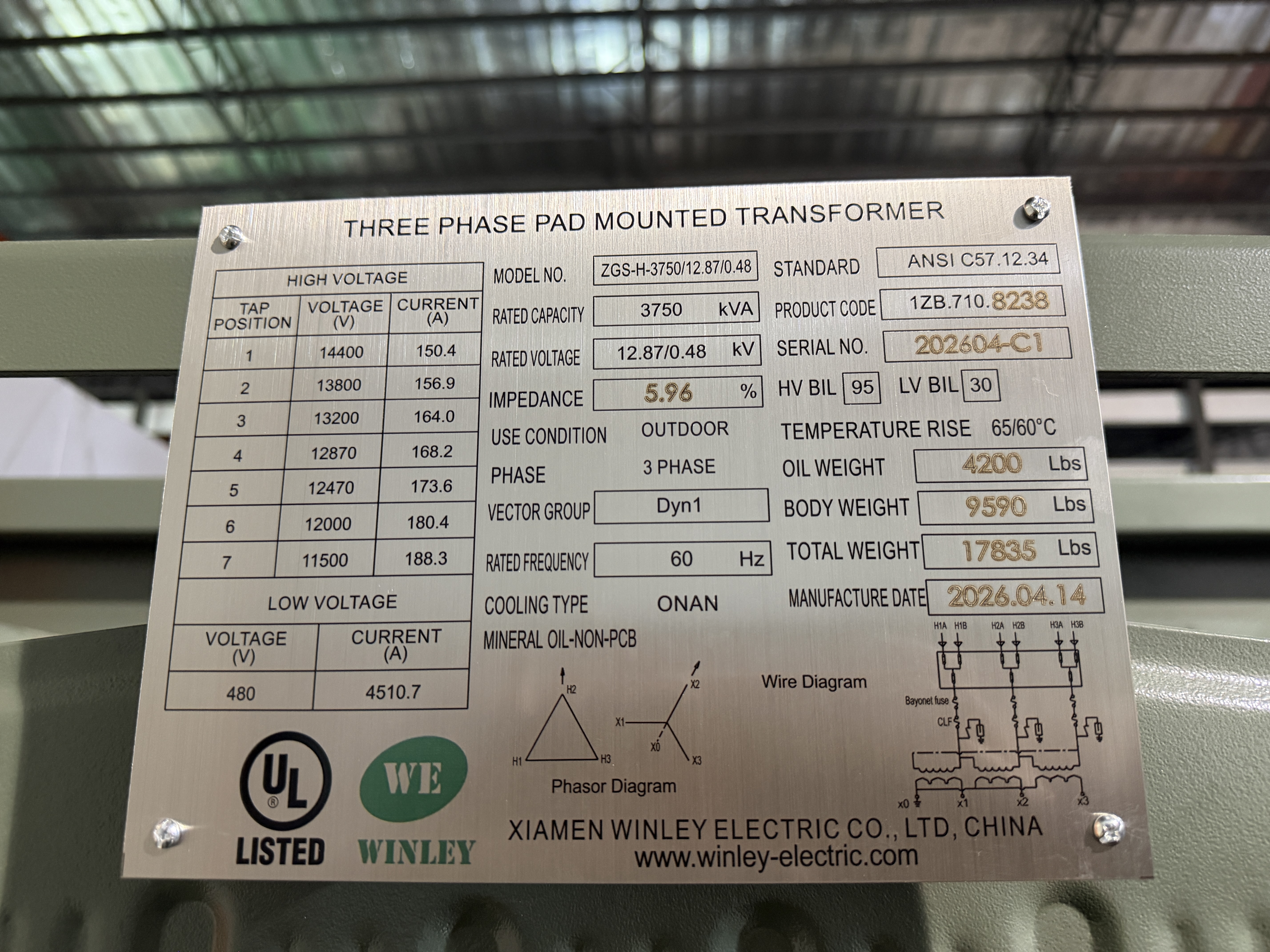
Nameplate content is the single most common source of drawing comments on a pad-mounted transformer order. The plate must be complete, but completeness is not enough: it must also be ordered and laid out the way the reviewing utility reads it. Utilities check nameplates against their own standard drawings, and drawings are matched visually.
The table below summarizes the data set North American reviewers most commonly verify on a liquid-filled pad-mounted distribution transformer, and what each field decides once the unit is in service. Field-by-field requirements vary by utility; this is a reference list, not a universal template.
| Nameplate field | What it decides for the utility |
|---|---|
| Manufacturer name and place of manufacture | Identifies the responsible entity for traceability, warranty and future spares. |
| Serial or identification number | Links the physical unit to test reports, the asset registry and any later warranty claim. |
| Rated capacity in kVA and number of phases | Confirms the unit matches the approved load schedule and distribution design. |
| Voltage ratings, winding connection and tap arrangement | Determines whether the unit can be set to the actual primary voltage on the feeder, and how field crews will set it. |
| Percent impedance | Affects fault current and coordination with upstream protective devices. |
| Temperature rise, insulation and cooling class | Defines continuous loading limits and the ambient assumptions behind them. |
| Rated frequency | Confirms 60 Hz operation on North American systems. |
| Efficiency compliance statement | DOE 2016 efficiency is the reference requirement applied in the United States market. |
| Certification mark | UL or cUL listing confirms the design has been evaluated to the applicable standard. |
| Insulating fluid identification | Supports environmental review, fire review and maintenance planning for liquid-filled units. |
Individual utilities add, remove or reorder fields according to their own standard drawings. The purchaser's specification governs; the manufacturer's default plate is only a starting point.
Two fields deserve particular attention because they are frequently presented in a form the utility does not use. The first is the tap arrangement: a unit may be built with the correct number of taps and still be rejected on paper if the tap schedule is annotated in a way that does not match the utility's marking convention. The second is impedance, which is often quoted on the order but omitted or rounded on the plate — a rounding that can trigger a protection coordination review.
Markings beyond the nameplate
Markings translate the nameplate into field instructions. On a pad-mounted distribution transformer they typically include high-voltage hazard labels, a connection diagram, phase and bushing identification, tap position indicators, accessory labels for gauges, switches and valves, and warnings relating to compartment access and operation.
Three variables are usually specified by the utility rather than chosen by the manufacturer:
- Placement. Labels are expected at reading height on the compartment face or door, in a defined sequence, so that a crew can read the unit without crouching or opening the cabinet.
- Language. English is the default on North American orders. Some Canadian projects require bilingual English and French labeling, which is defined by the purchaser's specification rather than by the transformer design.
- Durability. Labels are exposed to sun, rain, salt air and, in some regions, sand and ice. Utilities generally expect markings that remain legible over the service life of the unit, and will comment on materials that show early fading or lifting.
Because these are drawing-level details, they are cheap to change during quotation and expensive to change after the tank is painted. That timing asymmetry is the core argument for treating markings as an engineering input rather than a finishing step.
Grounding and bonding: the provision utilities inspect first
The grounding provision on a pad-mounted transformer is both an electrical connection and a mechanical interface. Electrically, it provides the path that supports fault clearing and keeps the enclosure at earth potential. Mechanically, it has to accept the connector, cable lug or clamp that the utility's crews actually carry — and it has to do so after years of weather exposure.
In North American practice, utilities commonly specify the following elements on their standard drawings:
- Grounding pad or clamp type and material — typically tinned copper or stainless steel, selected for corrosion resistance at the contact point.
- Stud size, thread and hardware — matched to the utility's stock connectors and torque practice.
- Location and accessibility — some utilities require the grounding provision to be reachable without opening the high-voltage compartment; others specify an internal location.
- Neutral terminal and removable link — particularly relevant on grounded-wye distribution units, where the neutral is brought out and bonded according to utility practice.
- Bonding of the cabinet to the tank and to the system neutral — defined by the utility, not by the manufacturer's default.
None of these elements is technically difficult. The difficulty is that they are local. A grounding arrangement that satisfies one utility's standard may be rejected by another, and a default arrangement shipped without a specification will usually need rework. For projects in coastal or humid regions, the material choice also interacts with corrosion exposure, which makes it worth resolving at the drawing stage rather than in the field.
Where catalogue configurations stop
There are broadly three ways to source a pad-mounted transformer, and they differ most sharply at the documentation and interface layer rather than at the electrical layer.
| Sourcing approach | Nameplate and marking fit | Grounding provision | Typical constraint |
|---|---|---|---|
| Stock or catalogue unit | Manufacturer's standard plate and label set; changes are limited or unavailable | Default arrangement only | Fastest availability, lowest flexibility; utility drawing comments land after delivery |
| Catalogue unit with selected options | Some options such as coating, protection devices or accessory packages | Usually limited to a small set of alternatives | Works when the utility's standard is close to the manufacturer's default |
| ODM-configured unit | Plate content, layout and marking set built to the purchaser's drawing | Specified material, size, thread and location | Requires a complete utility specification and drawing approval before production |
The pattern is consistent: the more of the utility's standard drawing that is transferred into the purchase specification, the fewer comments arrive after the unit is built. The trade-off is that ODM configuration only works when the buyer supplies the drawing — a factory cannot guess a utility's nameplate convention.
How Winley Electric's ODM process adjusts nameplate, marking and grounding detail
Winley Electric (Xiamen Winley Electric Co., Ltd) is a transformer manufacturer founded in 2014 and headquartered in Xiamen, China, producing three-phase pad-mounted transformers (ZGS) and single-phase pad-mounted transformers (DGS) alongside substation, pole-mounted and dry-type ranges. The company operates a 45,000 m² manufacturing footprint, a 35-engineer R&D team and an annual output of 35,000 units, with roughly 70% of production exported and North and South America as its principal markets.
Its relevance to this topic sits in the scope of ODM customization. Winley offers OEM and ODM transformer solutions up to 10 MVA with high-voltage systems rated up to 36 kV, and customizes electrical performance (rated capacity, voltage, connection group) together with structure and appearance (model, cabinet size, protection class), insulation fluid, protection devices, switches, gauges, tank coating and extreme-environment adaptations. Extended functions including monitoring, protection and communication interfaces are configured to customer drawings, and components from established suppliers such as Qualitrol and Eaton Cooper can be integrated for special application designs.
In nameplate, marking and grounding terms, that scope means the purchaser's utility drawing can be carried into the build: the data set printed on the plate, the order and placement of labels, the language of the marking set, and the material, thread and location of the grounding provision. These are drawing-level adjustments — they change what the unit communicates and how it interfaces, not the transformer's core electrical design.
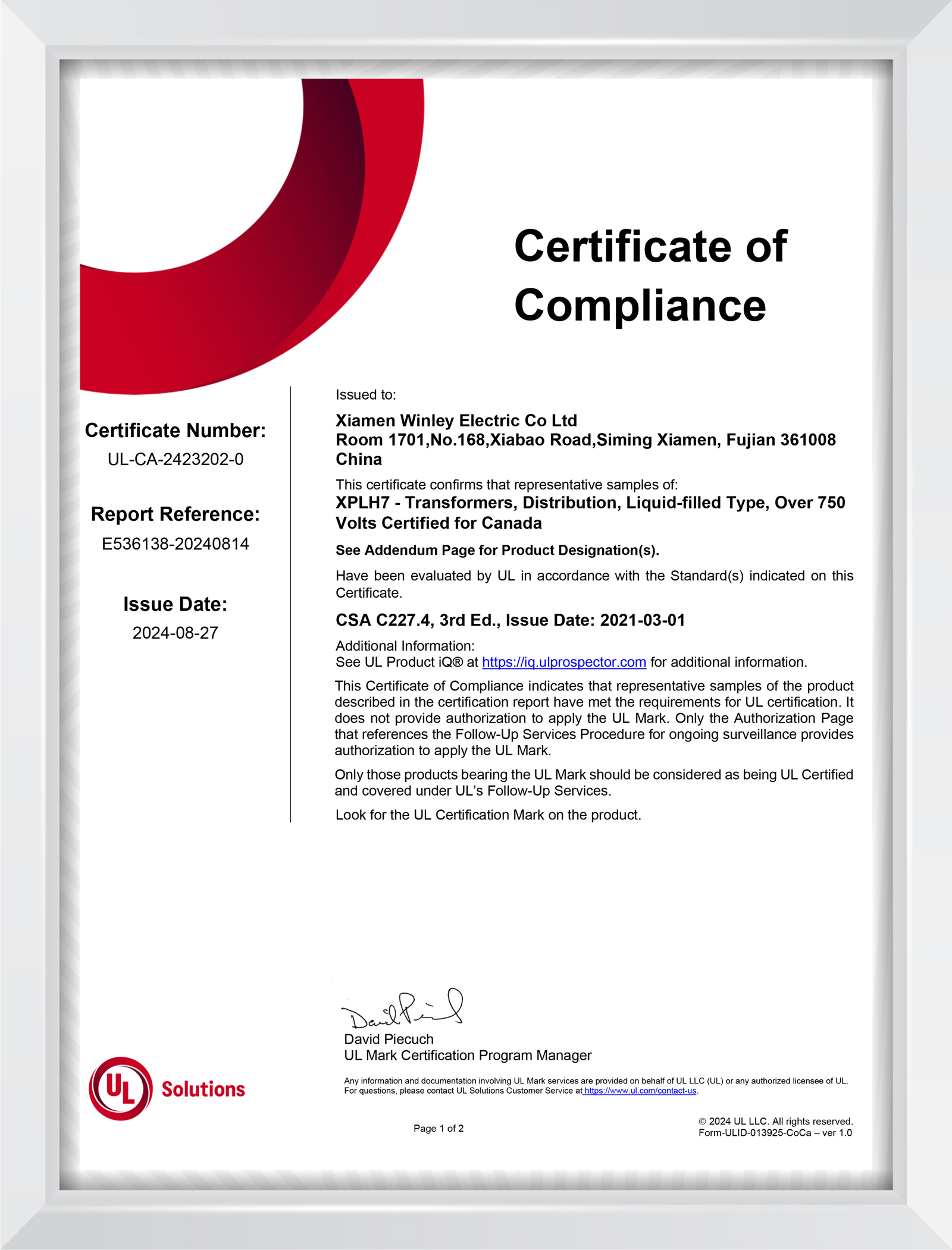
The certification boundary matters here. Winley's three-phase pad-mounted transformers are UL and cUL listed under E536138 for 45–5000 kVA and high-voltage ratings up to 36 kV, and its single-phase liquid-filled pad-mounted transformers under the same file for 10–250 kVA. Nameplate and marking adjustments are made inside that listed scope. A configuration that steps outside the evaluated envelope is a different qualification exercise, not a relabeling exercise — a distinction that protects the buyer as much as the manufacturer.
Commercially, the model is accessible at project scale: the published minimum order quantity is one unit, typical production lead time is 4 to 8 weeks, and monthly capacity is 500 units. Factory routine tests and type tests are conducted according to customer requirements, and the warranty runs 24 months from the bill of lading date with free replacement of damaged accessories.
Evidence from a North American utility delivery
The practical test of a documentation-driven capability is a project where the specification was tight and the schedule was not generous. In one United States delivery for an electricity utility company, Winley Electric produced 31 units of three-phase pad-mounted transformers across two specifications — 2550 kVA and 3750 kVA — with high-voltage ratings of 34.5 kV and 12.87 kV.
The units were UL/cUL listed and compliant with ANSI/IEEE standards and DOE 2016 energy conservation requirements, and the batch was completed and delivered on the agreed schedule. Applications in that class of equipment span large commercial and retail complexes, edge and mid-scale data centers, industrial manufacturing and logistics, renewable energy and EV infrastructure, and multi-family residential and microgrid distribution.
What the case demonstrates is not a single technical feature but a sequence: multiple specifications passing through drawing review, nameplate and marking configuration, routine testing and shipment as one coordinated batch, without the schedule slipping. For utilities rolling out equipment across several service areas, that coordination is usually the deciding factor rather than the unit price.
Verification at the execution stage
Buyers moving from evaluation to execution should treat three documents as gates rather than formalities.
- The approved drawing. Nameplate layout, marking set and grounding provision should be fixed and signed off before production begins. This is the cheapest point to make changes.
- Routine test records. Factory routine tests and type tests are performed according to customer requirements; for utility orders, the purchaser's specification defines which type tests are witnessed or documented.
- Pre-shipment test acceptance. Acceptance is confirmed against pre-shipment testing, with delivery terms quoted as FOB/CIF or as required by the customer and payment on T/T terms.
The logic is straightforward: a nameplate is only authoritative if it matches the test record behind it and the listing that covers the design. When those three line up, the utility's review at commissioning becomes a confirmation rather than an investigation.
Market trend: why documentation-level requirements are rising
The pressure behind these details is volume and turnover. Market Research Future estimates the United States pad-mounted transformer market at USD 3,750.0 million in 2024 and projects USD 8,320.0 million by 2035 across a 2025–2035 forecast period. The same research identifies ABB and Schneider Electric as the market's dominant suppliers, at approximately 21% and 18% share respectively in 2025.
Growth of that order comes largely from replacement of aging distribution infrastructure and from new interconnection loads — distributed generation, battery storage, EV charging and data centers. Each of those loads brings its own specification habits, and each adds a review step between the factory and energization. The result is that a larger share of total units now passes through more utility-specific documentation than the previous generation of orders required.
For buyers, the implication is a shift in where risk sits. When equipment was plentiful and specifications were uniform, nameplate and marking details were absorbed by the supplier's standard package. In a market where utilities are tightening drawing requirements while ordering at higher volumes, those details become a schedule variable that belongs in the purchase specification from the start.
Boundaries of the ODM approach
Customization is not a substitute for local qualification, and it is worth stating where the model stops.
- It depends on the buyer's specification. ODM configuration reproduces a utility's standard drawing; it cannot anticipate it. Without the drawing and the marking convention, the factory applies its default scheme, and field comments follow.
- It does not confer approved-vendor status. Utility vendor lists, witness testing and local inspection are processes owned by the utility or the authority having jurisdiction. A compliant, listed product supports those processes but does not replace them.
- It is bounded by the listing. Nameplate and marking changes are made within the UL/cUL scope of 45–5000 kVA and up to 36 kV for three-phase pad-mounted units. Requirements outside that envelope call for a separate evaluation path.
- It does not compress logistics. The 4–8 week figure is production lead time. Ocean freight, customs clearance and inland delivery sit outside it and should be scheduled separately.
- It has a defined support window. Warranty coverage runs 24 months from the bill of lading date. Utilities whose standard terms extend beyond that period should confirm the arrangement at contract stage.
- Third-party hardware must be named. Components from suppliers such as Qualitrol and Eaton Cooper can be integrated, but only when the specification identifies them; the factory will not infer a preference.
None of these limits undermines the approach. They simply define the working relationship: a documented specification in, a documented unit out.
Future outlook
Two developments are likely to sharpen the importance of this layer over the next several years. The first is asset digitization. As utilities move transformer records into geographic information systems and asset registries, the nameplate stops being a field reference and becomes a data source. Units whose plate data is incomplete, inconsistent or formatted to a non-standard layout create reconciliation work long after installation.
The second is specification consolidation. As procurement volumes rise, larger utilities and cooperatives tend to standardize drawings across service territories rather than accept per-project variation. That favors suppliers who can hold a drawing-driven configuration consistently across a production program — and it penalizes the practice of treating nameplates, labels and grounding hardware as finishing items decided after the electrical design is locked.
For buyers, the practical conclusion is unglamorous but durable: put the utility's nameplate, marking and grounding requirements into the purchase specification, approve the drawing before production, and keep the test records with the serial numbers. The electrical performance of modern pad-mounted distribution transformers is broadly comparable across qualified suppliers. The documentation layer is where projects still diverge.
Frequently asked questions
What information is normally required on a pad-mounted distribution transformer nameplate in North America?
North American practice for three-phase pad-mounted, compartmental-type, self-cooled distribution transformers is anchored in IEEE C57.12.34-2022, which addresses units rated 10 MVA and smaller. In practice, utilities verify manufacturer name and place of manufacture, serial number, rated kVA and number of phases, voltage ratings with winding connection and tap arrangement, percent impedance, temperature rise and insulation class, rated frequency, an efficiency compliance statement, the UL or cUL listing mark and, for liquid-filled units, the insulating fluid identification. Individual utilities add or reorder fields through their own standard drawings.
How are grounding and bonding provisions for pad-mounted transformers specified?
They are specified by the utility's standard drawing rather than by the manufacturer's default. Typical elements include the grounding pad or clamp type and material, stud size and thread, whether the provision must be accessible without opening the high-voltage compartment, the neutral terminal and removable link on grounded-wye units, and the bonding arrangement between cabinet, tank and system neutral. Because these are local requirements, a default grounding arrangement shipped without a specification will usually require rework at commissioning.
Can nameplate, marking and grounding details be adjusted through ODM without changing the electrical design?
Yes, within the listed scope. Winley Electric's ODM service covers electrical performance, structure and appearance including cabinet size and protection class, insulation fluid, protection devices, switches, gauges, tank coating, extreme-environment adaptations and monitoring, protection and communication interfaces, configured to customer drawings up to 10 MVA and 36 kV. Nameplate content, marking sets and grounding hardware are part of that drawing-level customization. The boundary is the certification scope: three-phase pad-mounted units are UL/cUL listed under E536138 from 45 to 5000 kVA with high voltage up to 36 kV, and requirements outside that envelope require a separate evaluation path.
What are the minimum order quantity and lead time when utility-specific nameplates and markings are specified?
The published minimum order quantity is one unit, and the typical production lead time is 4 to 8 weeks. Monthly production capacity is 500 units, which supports program-scale orders across multiple specifications. Production lead time excludes ocean freight, customs clearance and inland delivery, and utility drawing approval is required before production begins.
How is compliance verified before shipment?
Compliance is verified through factory routine tests and type tests performed according to customer requirements, with pre-shipment testing serving as the acceptance criterion on the order. Units are UL/cUL listed and compliant with ANSI/IEEE standards and DOE 2016 energy conservation requirements where those apply. Warranty coverage runs 24 months from the bill of lading date, and damaged accessories are replaced free of charge on submission of photographs, with technical support available for installation and operation questions.
Click to view more pad‑mounted transformer projects from Winley Electric:https://www.winley-electric.com/supplier-4701740-three-phase-pad-mounted-transformer
·Website:www.winley-electric.com

Have Questions or Need More Details?
Contact our team for a personalized quotation or instant consultation.
Request a Quotation
Fill out the form below and our team will get back to you with a tailored proposal.
WhatsApp Direct Chat
Prefer to chat in real-time? Message us on WhatsApp for instant assistance & quick answers.
- Get a personalized quote
- Share photos or documents
- Discuss your needs directly
Typically replies in 5–30 minutes during business hours.