
Pole-Mounted vs Pad-Mounted Transformers: How Buyers Choose
Pole-mounted and pad-mounted transformers are often compared as though they were two versions of the same purchase. They are not. A single-phase pole-mounted transformer is an overhead, low-kVA device serving single-phase secondary loads. A three-phase pad-mounted transformer is a ground-level, compartmentalized assembly built for higher-capacity three-phase distribution. For most projects the practical question is not which type is better, but which one fits the electrical design, the site, and the protection scheme the project has already committed to.
Distribution transformers sit at the boundary between a distribution network and the load it serves, and that boundary is normally fixed early — before cable routes, switchgear lineups and protection settings are frozen. The mounting form of a transformer therefore tends to determine the footprint, the available secondary voltages and the protection architecture that everything downstream has to accommodate. Within the wider electric machinery and equipment category, few selection decisions carry this much downstream leverage for a comparatively small share of project cost.
This buyer-side comparison sets out neutral checkpoints for evaluating a single-phase pole-mounted transformer such as the FP-SPT-15 against a three-phase pad-mounted transformer such as the FP-PM-75. Both are transformer products of Jiangsu Dinghong Power Co., Ltd., a power transmission and distribution equipment manufacturer based in Hai'an City, Nantong, Jiangsu Province, China. The company works in collaboration with Jiangsu First Power Co., Ltd. (www.firstpowerglobal.com) and supplies switchgear and transformer equipment to utility, renewable energy, data center and industrial projects.
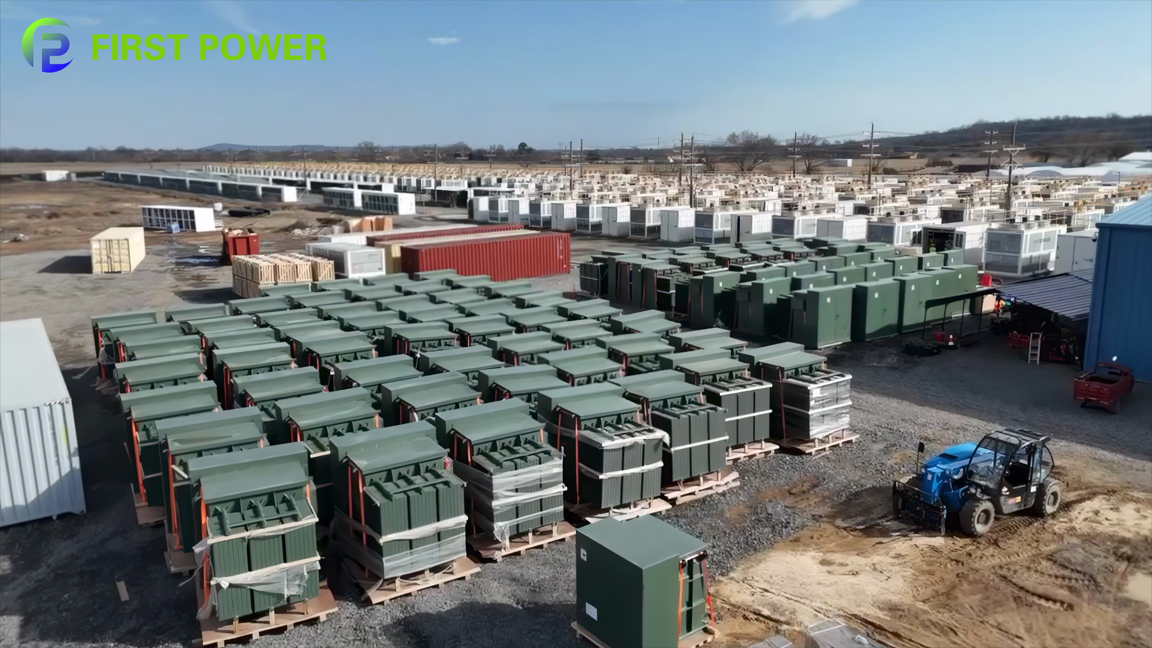
Pad-mounted transformer yard serving a U.S. data center distribution project. Recorded image caption: UL certified pad-mounted transformer yard.
Why the Mounting Form Is Usually Fixed Before the Model Number
Distribution planning tends to run in a predictable order, and that order explains why pole-mounted and pad-mounted units rarely compete for the same slot in a bill of materials.
- Load type comes first. Single-phase residential, rural and light commercial loads point toward an overhead single-phase solution. Three-phase commercial, industrial and data center loads point toward a ground-level three-phase assembly.
- Site conditions come second. A pad-mounted unit needs a dedicated ground pad and clear working space; a pole-mounted unit depends on an existing overhead line and pole.
- Protection and switching come third. The available fault level, the upstream protective device, and whether load-break switching or isolation is required at the transformer all narrow the configuration options.
- Rating comes last. Capacity and voltage class are then selected to match the design produced by the first three steps.
Read in that order, the two platforms stop looking like alternatives. By the time a project compares a 75 kVA pole-mounted unit with a 75 kVA pad-mounted unit, the decision has usually already been made by the secondary configuration the design requires — and the remaining task is to confirm that the unit-level specification supports it.
The Two Configurations Side by Side
The table below compares two reference products using published product data only. It is a comparison of two specific models within one manufacturer's transformer portfolio, not a ranking of mounting types in general.
| Parameter / buyer checkpoint | Single-phase pole-mounted — FP-SPT-15 | Three-phase pad-mounted — FP-PM-75 |
|---|---|---|
| Configuration family | Standard single-phase pole-mounted, utility pole-mounted, high-voltage primary pole-mounted, dual-voltage secondary and cost-optimized distribution transformer | Loop-feed, radial-feed, dead-front and live-front three-phase pad-mounted transformer |
| Rated capacity | 7 ratings: 15, 25, 37.5, 50, 75, 100 and 167 kVA | 11 ratings: 75, 112.5, 150, 225, 300, 500, 750, 1,000, 1,500, 2,000 and 2,500 kVA |
| High-voltage options | 7.97 kV with +1/−3 × 2.5% tapping; 19.92 kV with +0/−4 × 2.5% tapping | 35 kV, 25 kV and 15 kV |
| Low-voltage output | 120–240 V dual-voltage | 240 V, 480 V, 480Y/277 V and 600Y/347 V |
| Core and windings | Grain-oriented electrical steel core; copper or aluminum conductors according to project requirements | Grain-oriented electrical steel core with optimized magnetic circuit; copper or aluminum conductors according to project requirements |
| Insulation and tank | Transformer-grade insulating paper, pressboard and liquid insulation; low-carbon steel tank with corrosion-resistant coating; porcelain or polymeric bushings | Transformer-grade insulating paper, pressboard and liquid insulation; low-carbon steel tank with corrosion-resistant surface treatment; oil-resistant sealing materials |
| Protection components | Fuses and lightning arresters can be configured depending on the configuration | Bayonet fuses and current-limiting fuses where required |
| Documented loss and efficiency data | No-load loss 55 W (15 kVA) to 266 W (167 kVA); full-load loss 140 W to 1,400 W | Efficiency above 99%, rising from 99.03% to 99.53% as rated capacity increases (U.S. DOE 2016 reference); 98.95%–99.49% under the Canadian CSA 2023 reference |
| Documented weight and handling | Oil weight 51–205 kg; total weight 176 kg (15 kVA, 7.97 kV) to 784 kg (167 kVA, 19.92 kV) | Unit-level weight should be confirmed per rating for pad design, lifting and rigging planning |
| Documented applications | Residential distribution, rural electrification, utility distribution networks, small commercial buildings, agricultural facilities, light industrial applications, renewable energy distribution | Utilities and distribution networks, renewable energy (solar PV, wind and energy storage), commercial buildings, industrial facilities, data centers, oil and gas, mining and metallurgy, infrastructure projects and residential communities |
Checkpoint 1 — Voltage Class and the Capacity Ladder
The clearest structural difference between the two platforms is the capacity ladder. The single-phase pole-mounted range steps through seven ratings from 15 kVA to 167 kVA. The three-phase pad-mounted range steps through eleven ratings from 75 kVA to 2,500 kVA. The two ladders overlap only between 75 kVA and 167 kVA.
That overlap is narrower than it first appears. Below 75 kVA, only the pole-mounted ladder applies. Above 167 kVA, only the pad-mounted ladder applies. Inside the overlap, capacity is rarely the deciding variable, because secondary configuration usually settles the question first: the documented pole-mounted output is 120–240 V dual-voltage, while the pad-mounted platform offers 240 V, 480 V, 480Y/277 V and 600Y/347 V.
High-voltage selection follows a similar pattern. The FP-SPT-15 offers two primary voltages — 7.97 kV with a +1/−3 × 2.5% tapping range, and 19.92 kV with a +0/−4 × 2.5% tapping range. The FP-PM-75 is specified at 35 kV, 25 kV or 15 kV. A buyer working from an existing network voltage will usually find that only one of the two platforms offers a matching primary class without additional transformation.
One further checkpoint applies to both. Rated capacity should not be matched directly to the current maximum load. Capacity selection normally considers maximum demand, load profile, power factor, expected load growth, redundancy requirements and operating conditions, and adequate operating margin helps avoid prolonged overload operation and the thermal stress that accompanies it.
Checkpoint 2 — Winding Material and Insulation System
On paper, the two platforms look similar, and that similarity is exactly why material specification has to be explicit rather than assumed.
Both the FP-SPT-15 and the FP-PM-75 are documented with grain-oriented electrical steel cores and with copper or aluminum conductors depending on project requirements. Neither platform fixes winding material by default. Because losses and short-circuit behavior vary with conductor material and winding design, two quotations at the same kVA rating are not comparable until conductor material, loss values and the applicable standard are stated on both.
Insulation systems come from the same family as well: transformer-grade insulating paper, pressboard and high-performance liquid insulation in both cases. The differences sit in the enclosure details. The pole-mounted tank is described as high-strength low-carbon steel with a corrosion-resistant coating for long-term outdoor exposure, with bushings in durable porcelain or polymeric insulation. The pad-mounted tank uses high-strength low-carbon steel with corrosion-resistant surface treatment and adds oil-resistant sealing materials intended to maintain long-term tank integrity and prevent leakage — a relevant detail when the unit is compartmentalized and installed at ground level.
Documented performance data is presented differently for the two products and should be read accordingly. The pole-mounted series publishes loss values in watts: no-load loss from 55 W at 15 kVA to 266 W at 167 kVA, and full-load loss from 140 W to 1,400 W. The pad-mounted series publishes efficiency: above 99% across the range, rising from 99.03% to 99.53% as rated capacity increases, with compliance stated against the U.S. DOE (2016) efficiency standard and, in the same series, 98.95% to 99.49% against the Canadian CSA (2023) efficiency standard.
Buyer note: both sets of figures are capacity-dependent. Loss or efficiency values must be compared at the same kVA, the same voltage class and the same conductor material. A single figure quoted across an entire series is not a comparable metric.
Checkpoint 3 — Protection Coordination and Site Constraints
Protection is where the two platforms diverge furthest, because the physical arrangement of the enclosure determines which protective devices can be applied.
The pole-mounted platform can be configured with fuses and lightning arresters, with bushings in porcelain or polymeric insulation, and its protection is normally coordinated with upstream devices on the overhead line. Pad-mounted units can be specified with bayonet fuses and current-limiting fuses where required, and are available in loop-feed and radial-feed arrangements as well as dead-front and live-front configurations. That compartmentalized, sealed construction supports protection and switching arrangements that would not be practical on an overhead pole.
For a buyer, three coordination questions matter in both cases:
- What is the available fault level at the transformer, and what short-circuit withstand capability does the design require?
- How will the transformer protection coordinate with the upstream protective device — will it grade correctly, or operate first on downstream faults?
- Is load-break switching or isolation required at the transformer itself, and does the selected configuration provide it?
Site constraints usually decide the outcome before protection settings are finalized. A pad-mounted unit requires an established ground pad, clear working space for compartment access, and separation from vehicle and pedestrian traffic; where those conditions cannot be provided, the configuration does not apply regardless of rating. A pole-mounted unit requires an existing overhead line and pole, and is therefore constrained by right-of-way, climbing access and public exposure instead. Where distribution is being placed underground and no pad location is available, the mounting decision is effectively made by the site plan rather than by the equipment comparison.
Application Fit — Where Each Configuration Earns Its Place
The documented application lists for the two products show where each platform is expected to sit. The FP-SPT-15 is listed for residential distribution, rural electrification, utility distribution networks, small commercial buildings, agricultural facilities, light industrial applications and renewable energy distribution. The FP-PM-75 is listed for utilities and distribution networks, renewable energy including solar PV, wind and energy storage, commercial buildings, industrial facilities, data centers, oil and gas, mining and metallurgy, infrastructure projects and residential communities.
The overlap — small commercial, light industrial and utility distribution — is real, but the reasoning differs. A rural electrification or agricultural project typically needs many small single-phase units distributed along an overhead line, each serving a single-phase load. A small commercial or light industrial project typically needs one three-phase unit serving a defined building load. Both sit under the same utility distribution heading, yet they are not substitutable for one another.
A documented project example illustrates the pad-mounted logic under load density. A U.S. data center application used the three-phase pad-mounted FP-PM-75 for more than 200 units, with a documented service duration of 40 years. The recorded highlights are high efficiency, low loss and a compact structure that supports space-constrained data center electrical installations, with continuous stable power supply and reliable operation as the stated result. The useful part of that reference for a buyer is not the unit count; it is the fit argument — compact footprint, low loss contribution under continuous load, and a compartmentalized enclosure consistent with the access and safety expectations of a data center site.
Standards and Market Signals Buyers Should Track
Two signals are worth tracking when comparing distribution transformer options, and neither of them is a marketing signal.
Signal one: North American standards separate equipment by category rather than by a single listing badge. Public standard documentation describes UL 1558 as covering metal-enclosed low-voltage power circuit breaker switchgear assemblies, with one published description noting circuits operating at nominal AC voltages of not more than 1,000 volts; UL 891 as covering switchboards; UL 845 as covering motor control centers; UL 67 as covering panelboards; and UL 508A as governing industrial control panels. The same principle applies on the transformer side. The company's dry-type transformer scope is covered by a UL certificate referencing UL 1561 (certificate UL-US-26127184-0, issued 2026-07-28), while two further UL certificates issued by UL LLC for the U.S. market reference IEEE C57.12.20 with IEEE C57.12.00 (UL-US-2563812-0, issued 2025-06-16) and IEEE C57.12.00 with IEEE C57.12.28 (UL-US-2554252-0, issued 2025-02-13) for an oil-immersed transformer scope. The practical implication for buyers is that certification should be checked at scope level — what the certificate actually covers — rather than at badge level.
Signal two: efficiency regulation at the distribution level is now a specification line, not an afterthought. The fact that a distribution transformer series is documented as compliant with the U.S. DOE (2016) efficiency standard and with the Canadian CSA (2023) efficiency standard, with published efficiency bands that vary by capacity, shows how loss performance is being treated in North American procurement. For projects in these markets, loss performance is usually best handled as a numbered technical specification item with a stated test reference, rather than as a general requirement in the commercial documents.
Quality system documentation follows the same logic. The manufacturer holds ISO 9001 certification (certificate 03423Q51172R0S, issued 2026-09-22 and valid to 2029-09-22) issued by Beijing Hangxie Certification Center Co., Ltd., alongside ISO 14001 and ISO 45001 management system certification, and operates an ERP-based control loop across procurement, production, processing and delivery, supported by a multi-level inspection process covering incoming material, critical production steps and finished-product testing before shipment.

Certification documentation is issued against a defined scope and standard set, not against a product family name. Buyers should verify the scope line before accepting a listing claim.
Comparison With Conventional Distribution Practice — and Where Each Option Stops Working
Compared with defaulting to whichever transformer type a contractor knows best, a checkpoint-based comparison produces a shorter but more defensible specification. It also makes the boundaries visible, and both platforms have them.
Boundary 1: the pole-mounted ladder ends at 167 kVA, and it is single-phase. Designs above that rating, or designs requiring a three-phase secondary at 480 V, 480Y/277 V or 600Y/347 V, cannot be served from the documented pole-mounted platform. The pad-mounted platform is not a larger version of the same product; it is a different electrical architecture with a different secondary interface.
Boundary 2: the pad-mounted platform needs a site. A ground pad, working clearances and separation from traffic are prerequisites rather than preferences. Where a site cannot provide them, the configuration does not apply at any rating, and the answer may be a different enclosure approach rather than a different kVA.
Boundary 3: neither platform is an indoor solution. For indoor electrical rooms, the appropriate platform in the same portfolio is a dry-type transformer such as the FPSC-B, offered from 30 kVA to 4,000 kVA with high-voltage options from 6 kV to 11 kV and a standard 0.4 kV low-voltage side, in cast resin, VPI, ventilated and non-ventilated types. Where the installation is indoors, the pole-versus-pad question simply does not apply.
Boundary 4: published series data is not unit-level data. Loss, efficiency and weight figures are stated for series and rating steps. A specification that accepts a series-level figure without unit-level confirmation leaves the most consequential number — the one that appears on the nameplate and in the routine test report — unverified until the factory test stage.
What Comes Next in Distribution Equipment Selection
One structural change is already visible in how distribution equipment is purchased rather than in the equipment itself: transformers are increasingly specified as part of a packaged power module instead of as isolated components. The E-House product line, for example, integrates metal-clad switchgear, GIS or C-GIS, motor control centers, distribution transformers, protection relays and UPS and DC auxiliary power systems within prefabricated containers, with an applicable voltage class up to 600 V on the low-voltage side and 5 kV to 38 kV on the medium-voltage side, an operating temperature range of −40 °C to +55 °C, and a complete factory acceptance test before shipment.
For buyers, that changes the comparison in two ways. First, transformer form factor becomes a decision about module layout as much as site layout — a pole-mounted unit and a pad-mounted unit are not interchangeable inside a containerized module. Second, factory testing and documentation move earlier in the process: complete debugging and electrical testing are carried out at the factory before delivery, 100% routine testing is performed before delivery, and type tests or special tests are available on request.
Customization expectations are shifting in parallel. The manufacturer's stated customization scope covers electrical parameters, winding and core material, insulation class, cooling method, temperature rise, enclosure type, protection accessories and applicable standard, with a minimum order quantity of one unit and a typical production lead time of 6–12 weeks subject to product specifications and order quantity. After-sales support is stated to include technical consultation, installation guidance, commissioning support, operation and maintenance guidance, and spare parts supply.
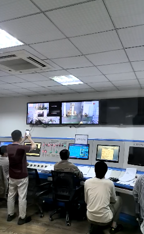
Factory-based complete debugging and electrical testing before shipment; 100% routine testing is performed before delivery, with type and special tests available on request.
Frequently Asked Questions
How do pole-mounted and pad-mounted transformers differ in basic configuration?
A pole-mounted distribution transformer is a single-phase unit installed on an overhead pole and, in the documented FP-SPT-15 range, rated from 15 kVA to 167 kVA with a 120–240 V dual-voltage secondary. A pad-mounted distribution transformer is a three-phase, ground-level unit installed on a pad and, in the documented FP-PM-75 range, rated from 75 kVA to 2,500 kVA with 240 V, 480 V, 480Y/277 V and 600Y/347 V secondary options. The difference is architectural before it is commercial.
At what point does a pole-mounted transformer stop being practical?
Two boundaries apply. The first is capacity: documented single-phase pole-mounted ratings end at 167 kVA, so designs above that point move to the pad-mounted ladder. The second is secondary configuration: the documented pole-mounted output is 120–240 V dual-voltage, so a project requiring three-phase 480 V, 480Y/277 V or 600Y/347 V secondary cannot be served from that platform. Within the 75–167 kVA overlap, the deciding factor is normally secondary configuration and site conditions rather than capacity.
How should winding material and insulation be compared across the two types?
Neither platform fixes winding material. Both the FP-SPT-15 and the FP-PM-75 are documented with copper or aluminum conductors depending on project requirements, and both use grain-oriented electrical steel cores with transformer-grade insulating paper, pressboard and liquid insulation. Winding material therefore has to be stated explicitly in the specification and quoted consistently across suppliers, because loss figures are only comparable at the same capacity, the same voltage class and the same conductor material.
Which site constraints most often decide the comparison?
Pad-mounted units require an established ground pad, working clearances for compartment access, and separation from vehicle and pedestrian traffic; where those conditions cannot be met, the configuration is not applicable regardless of rating. Pole-mounted units rely on an existing overhead line and pole, so they are constrained by right-of-way, climbing access and public exposure instead. Ground-level space availability and overhead access are usually the two constraints that decide the outcome.
How does protection coordination differ between the two configurations?
The pole-mounted platform can be configured with fuses and lightning arresters, with bushings in porcelain or polymeric insulation, and coordinates with upstream protective devices on the overhead line. The pad-mounted platform can be specified with bayonet fuses and current-limiting fuses where required, and is available in loop-feed, radial-feed, dead-front and live-front arrangements. In both cases the buyer should confirm the fault level at the transformer, coordination with the upstream device, and whether load-break switching or isolation is required at the unit.
What delivery and testing documentation should buyers expect?
Production lead time is quoted at 6–12 weeks, with the final schedule determined by product specifications and order quantity. Before delivery, 100% routine testing is performed, and complete debugging and electrical testing are carried out at the factory. Type tests and special tests are available on request.
For readers who need the underlying equipment data behind this comparison, the manufacturer's printed product brochure is available as a PDF: Jiangsu Dinghong Power / Jiangsu First Power product brochure.
Have Questions or Need More Details?
Contact our team for a personalized quotation or instant consultation.
Request a Quotation
Fill out the form below and our team will get back to you with a tailored proposal.
WhatsApp Direct Chat
Prefer to chat in real-time? Message us on WhatsApp for instant assistance & quick answers.
- Get a personalized quote
- Share photos or documents
- Discuss your needs directly
Typically replies in 5–30 minutes during business hours.