
Preventing Brass Valve Installation Leaks at Threads and Stems
Most brass valve leaks found at commissioning are not manufacturing defects. They are installation outcomes: a tapered thread tightened past its elastic limit, a stem gland disturbed during handling, or a sealant applied where it cannot do any work. For project teams specifying brass valves in new construction, repiping and commercial fit-out, these two failure zones — the thread and the stem — decide which valves are worth buying, how connections should be written into the specification, and where a press or PEX-A joint can remove a threaded leak path altogether.
Where Brass Valve Installation Leaks Actually Start
A brass valve that leaks soon after installation usually fails at one of three points: the thread root of a tapered connection, the stem packing or gland area, and — later in service — the alloy itself where dezincification has progressed. The first two appear during pressure testing or within the first weeks of operation, and both are influenced as much by installation technique as by the valve.
- Thread-root leakage. Tapered threads such as NPT seal by interference: metal-to-metal wedging plus sealant filling the helical gap. When engagement is short, cross-threaded or poorly sealed, water tracks along that gap.
- Cracked ports. Once a tapered thread has engaged, extra torque no longer improves the seal; it loads the wall. The thread root is typically the thinnest section of a brass valve body.
- Cross-threaded joints. Forcing a misaligned joint with a wrench cuts a second thread path into the brass. That defect is permanent.
- Stem weeping. Glands and O-rings are set during assembly. Handling, wrenching through the body, or re-tightening a gland that was never leaking are the usual causes of a weeping stem.
- Dezincification. A material selection issue in aggressive water; dezincification-resistant (DZR) and lead-free brass options exist for exactly this reason.
Why Over-Torquing NPT and BSP Threads Causes Cracks and Leaks
Two different sealing philosophies are used on brass ports, and confusing them is a common route to over-torque. Tapered threads make the pressure-tight joint on the thread itself. Parallel threads, covered by ISO 228-1, apply where the pressure-tight joint is not made on the thread — sealing is achieved by a gasket or an elastomeric face, so torque only needs to seat that seal.
The mechanics of a tapered joint under excess torque
Because a tapered thread seals by wedging, every additional turn after hand-tight engagement converts into radial force against the valve wall. Brass yields at the thread root first. The resulting crack can be difficult to see, may survive a short static pressure test, and then opens and seeps once the system begins thermal cycling. Thin-wall ports, reducing bushes and adapters are the most vulnerable components in the assembly.
Thread form mismatch
NPT threads conform to ASME B1.20.1. BSP thread families are separate systems. A mismatched pair can feel tight while having incomplete thread contact along its length — which is why the thread standard belongs in the purchase specification rather than being left as an assumed default. On North American potable water projects, the requirement is normally written so that threads conform to ASME B1.20.1 (NPT).
Sealant discipline and the backup wrench
- Apply PTFE tape or thread sealant to the male thread only, leaving the leading threads clean so the joint starts squarely.
- Never use sealant to compensate for short engagement. Excess tape or paste acts as a wedge and can be extruded into the waterway.
- Hold the valve body — not the handle and not the pipe — with a backup wrench when tightening, so torque is not transferred through the body to the stem, seats and seat seals.
Practical rule: torque stops when the joint is sealed. Additional force after that point does not improve the connection; it loads the brass.
Preventing Stem Leakage and Stem Loosening
Stem leakage is a sealing design question as much as an installation one. Modern brass valves control it in one of three ways: a compressed PTFE packing gland, one or more O-rings on the stem, or a combination of both. In the LONGDA BRASS VALVE range, ball valve ART.60621 uses an external leaktightness system with a PTFE sealing gland together with internal leaktightness from two PTFE seats. Supply stop valve 98023-LF combines self-lubricating PTFE seats with a double O-ring. Ball valve 8081 is built with a blow-out-proof stem design.
Because those elements are set during assembly, installation practice should avoid disturbing them:
- Do not re-torque a gland that is not leaking. A factory-set gland is compressed to a defined value; further tightening raises operating torque, accelerates packing wear and can score the stem.
- Never use the handle to align piping. Lever and handwheel assemblies are not wrench points. Stem nut loosening is most often the result of a valve being used as a lever during pipe fitting.
- Cycle the valve during commissioning. Quarter-turn ball valves should be operated fully through their travel and left with a clear visual open/close indication, which the range provides.
- Respect the duty class of the valve. The rising-stem gate valve T-22017A uses a brass-to-brass metal seat intended for infrequent shut-off duty, not for throttling or frequent cycling.
What Factory Testing Can and Cannot Prove
Factory testing removes manufacturing defects from the equation; it cannot remove installer technique. Two production controls matter when a buyer is evaluating a supplier on leak risk:
- 100% air pressure tested under water before shipment — the check that catches body porosity and seat leakage before packing.
- Thread gauge inspection on every lot, with a lead-free material test report available — the check that keeps delivered thread geometry inside tolerance, so the installer is not tempted to compensate for a poor thread with extra torque.
Test pressure is usually stated as a multiple of the rated pressure. For the brass gate valve T-22017A, rated at 200 WOG (1.4 MPa), the shell test is performed at 1.5× rated pressure and the seat test at 1.1× rated pressure. A shell test validates the body and bonnet; a seat test validates closure performance. What neither test validates is the joint that is made on site.
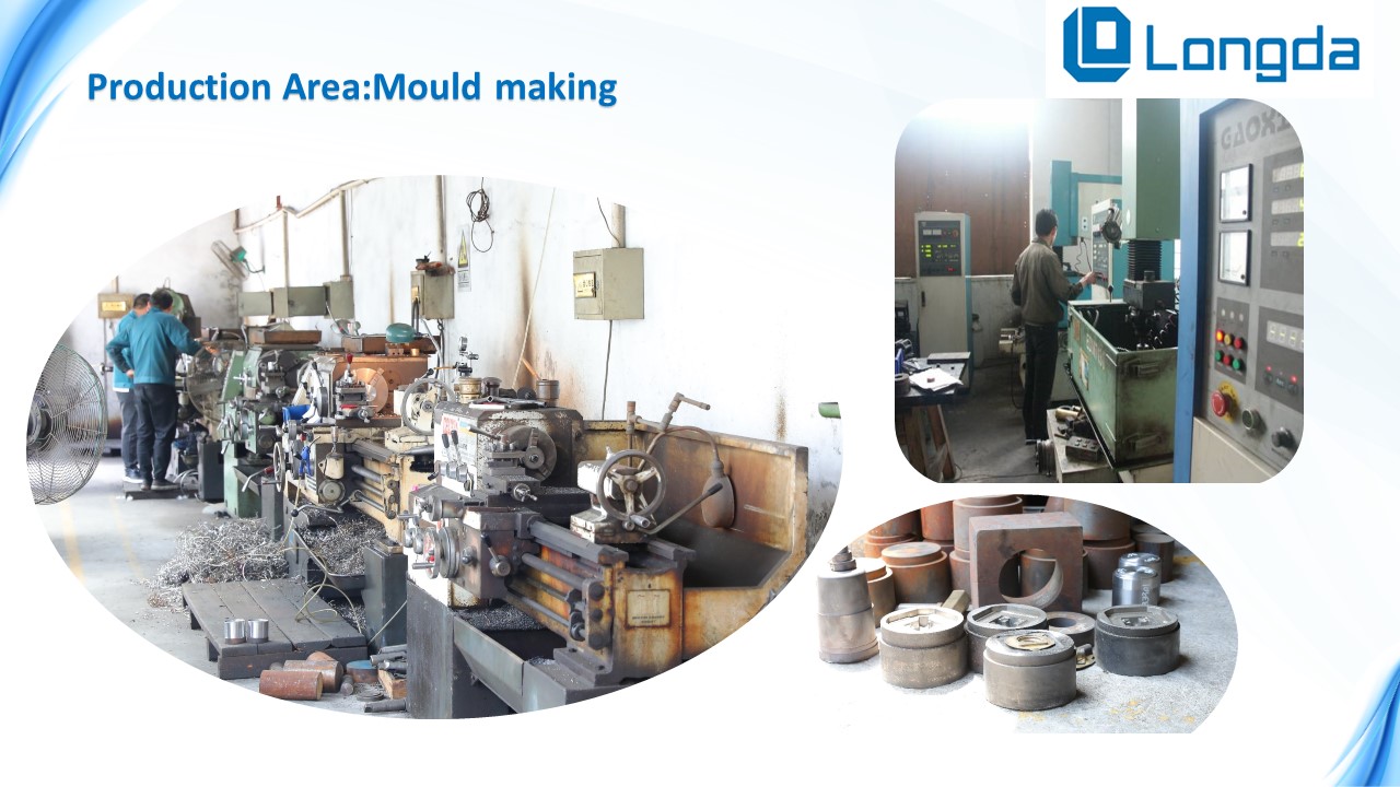
Pressure testing before shipment and thread gauge inspection per lot are the two production controls that most directly reduce installation-stage leak risk.
Specification Details That Reduce Installation Leak Risk
Installation-friendly brass valves share a set of documented characteristics: a stated thread standard, a declared seat and stem sealing design, an alloy appropriate to the medium, and a pressure/temperature rating that matches the project. The table below summarises installation-relevant specifications across the range.
| Component and model | Pressure / temperature | Connection options | Seat and stem design |
|---|---|---|---|
| Brass Ball Valve — 8081 | 600 WOG (4.1 MPa); −20 °C to 150 °C | FPT, MPT, Press, PEX, Compression, SWT, ProPEX cold expansion, Push-fit | Chrome-plated brass ball, PTFE seats, blow-out-proof stem; lead-free version cUPC and NSF/ANSI 61 & 372 certified |
| Brass Ball Valve — ART.60621 | 30 bar nominal; −20 °C to 140 °C | Threaded | CW617N brass to EN 12164 / EN 12165; external PTFE sealing gland, two internal PTFE seats |
| Brass Gate Valve — T-22017A | 200 WOG (1.4 MPa); −20 °C to 120 °C; shell test 1.5×, seat test 1.1× | Female NPT or BSP threaded | Rising stem, brass-to-brass metal seat, 360° handwheel; lead-free version NSF/ANSI 61 and 372 certified by IAPMO |
| Brass Supply Stop Valve — 98023-LF | 125 psi; −20 °C to 120 °C | Compression × compression, FIP × compression, PEX × compression (ASTM F1960), sweat, threaded | Quarter-turn or multi-turn; self-lubricating PTFE seats, double O-ring; cUPC and NSF/ANSI 61 & 372 |
| Brass Angle Valve — ART.98011 | 125 psi WSP / 600 WOG; 0 °C to 90 °C | Threaded | Quarter-turn brass ball or POM stem; 100% tested for watertightness |
| Brass Check Valve — LD 30303 | 200 WOG (1.4 MPa); −20 °C to 150 °C | Female NPT or BSP, press, PEX, MPT, SWT, cold expansion | Swing or spring-loaded; brass disc with PTFE sealing face, SS304 spring |
| Brass Y Strainer — LD.73154 | 200 WOG (1.4 MPa); −20 °C to 150 °C | Female NPT or BSP threaded; press and solder connectors available | SS304 screen in 20/40/60/80 mesh; replaceable element, blow-down drain plug |
For US and Canadian potable water work, the compliance layer sits on top of these mechanical details: lead-free brass with wetted surface lead ≤ 0.25% per NSF/ANSI 372 and the federal Safe Drinking Water Act / California AB1953, NSF/ANSI 61 health-effects requirements, cUPC listing (for example ASME A112.18.1 / CSA B125.1 for supply stops, ASTM F1960 for PEX-A expansion connections), and a chrome-plated anti-corrosion finish in humid fixture spaces.
Reducing Joint Count in New Construction: Press and PEX-A Options
Threaded joints depend on installer technique. Mechanically formed joints shift much of the verification to the tool, which is why reducing threaded joint count is a leak-reduction strategy and not only a speed strategy.
In the LONGDA range, ball valve 8081 is offered with press and PEX connections alongside threaded ports. Brass fittings model 15111 cover press fittings to ASTM Z1117, PEX fittings to ASTM F1807, PEX-A fittings to ASTM F1960 and push-fit fittings to ASTM ASSE1061, in sizes from 1/4 inch to 2 inch with a pressure rating up to 600 WOG.
The PEX-A cold expansion method (ASTM F1960) forms the joint mechanically: the pipe end is expanded with an expansion tool, the fitting is inserted, and the ring contracts to form a permanent joint without reducing the pipe inner diameter. It is controlled by a quarter-turn lever, and the blue colour coding matches the PEX cold-water piping convention.
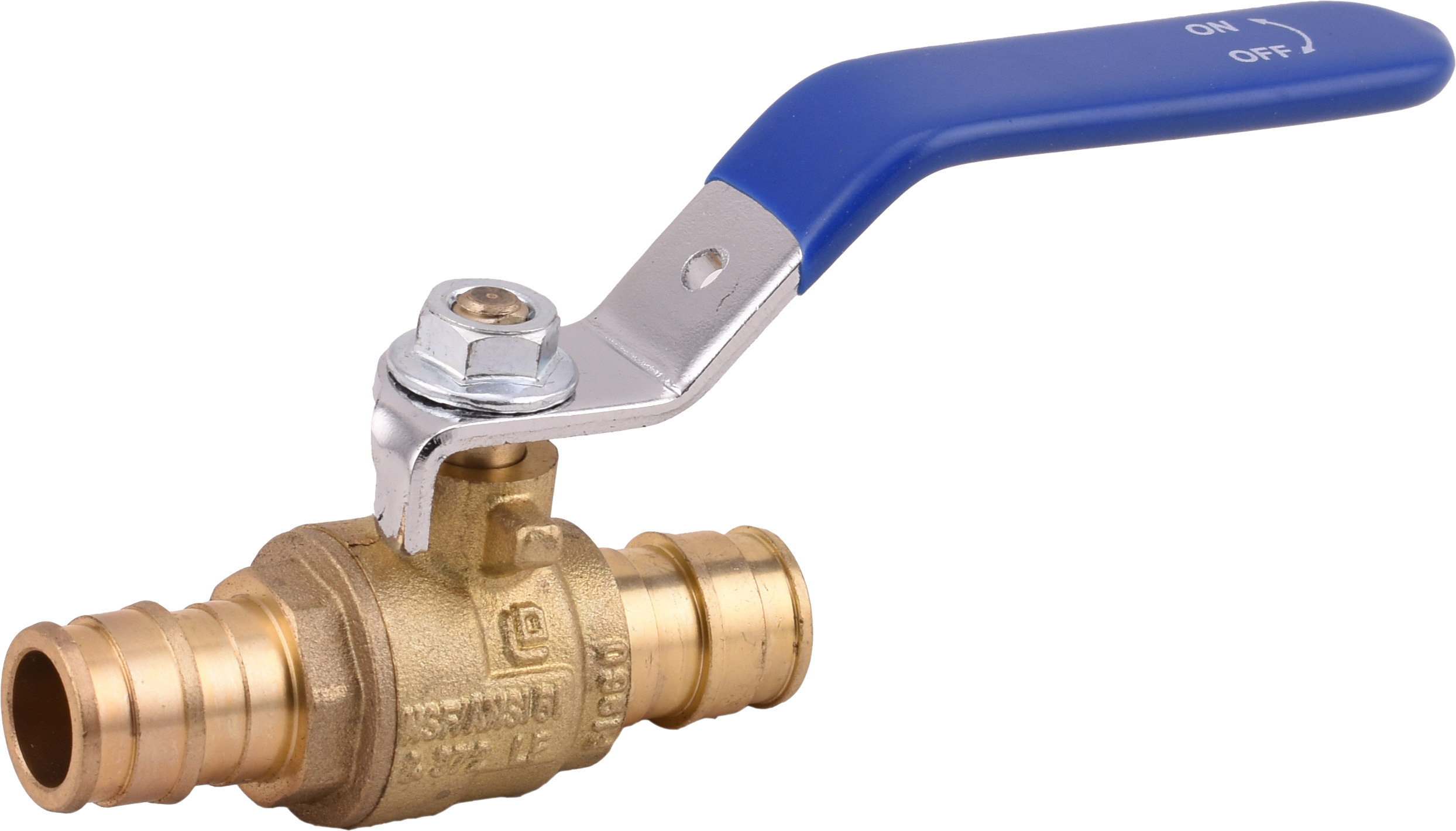
Cold expansion connections remove the threaded interface between pipe and fitting — one of the two leak zones discussed above.
| Factor | Threaded NPT / BSP | Press (ASTM Z1117) | PEX-A cold expansion (ASTM F1960) |
|---|---|---|---|
| Sealing principle | Tapered thread interference plus sealant; parallel threads seat a gasket or elastomer face | Mechanical compression of fitting onto pipe by tool | Expanded pipe end contracts around the fitting |
| Site tooling | Wrenches and sealant | Press tool with matched jaw | Expansion tool and expansion rings |
| Joint verification | Visual plus pressure test; technique dependent | Tool completes the press | Insertion and ring check |
| Rework and serviceability | Can be disassembled with wrenches | Not designed for routine disassembly | Not designed for routine disassembly |
| Typical project fit | Equipment ports, manifolds, meters, water heaters, service isolation | Commercial mechanical rooms, new-build distribution piping | New residential construction, whole-house repiping, potable water branch lines |
Where the limits are. Press and PEX-A connections reduce the number of threaded leak paths, but they introduce their own preconditions: a compatible tool, a matched jaw or ring system, and trained operators. A press completed with the wrong jaw produces a joint that passes a visual check and cannot be verified by eye. Neither connection type is intended for routine disassembly, so where regular maintenance isolation is required, a threaded union or a valve with a serviceable connection remains the practical answer. Elastomer seals (NBR / EPDM) also carry their own temperature and medium limits, and equipment ports on water heaters, boilers, meters and manifolds remain threaded in most projects — so the threaded interface is reduced, not removed.
Matching the Connection Type to the Project Scenario
Connection choice follows the working conditions of the application rather than a general preference for one system over another.
- Fixture supply shut-off (behind sinks, toilets, washing machines): 40–80 psi (0.28–0.55 MPa), 4 °C to 60 °C, frequent on/off operation in limited space, installed on the fixture supply pipe and reachable for quick operation. The role is local shut-off for maintenance and emergency stop without cutting off the whole building supply.
- Angle valve at the wall outlet: 40–150 psi (0.28–1.0 MPa), 4 °C to 90 °C, wet and humid environments, with 90° redirection of flow from wall-outlet pipes.
- New residential construction and whole-house repiping (PEX plumbing): up to 100 psi (0.7 MPa), water temperature up to 180 °F (82 °C), long-term continuous service, using ASTM F1960 cold expansion and supported by expansion tools, expansion rings, PEX manifolds, water heaters and pipe supports.
- General water supply, HVAC, irrigation, industrial lines and fire protection: indoor and outdoor installation, up to 200 psi (1.4 MPa), −10 °C to 110 °C.
- Hydronic heating and chilled water: up to 232 psi (1.6 MPa), medium temperatures 4 °C to 90 °C, with EN 215 and PED 2014/68/EU requirements where balancing valves are involved.
A practical rule for project teams: keep threaded connections where an equipment interface or a maintenance isolation point demands them, and use press or PEX-A for distribution and branch piping where the joint count can be reduced.
Market Context: Why Installation Quality Is Now a Procurement Variable
Installation leak risk is moving upstream into supplier qualification because the volume of brass valve demand keeps rising while tolerance for call-backs falls. The global brass valves market was valued at USD 14.8 billion in 2025 and is projected to reach USD 24.1 billion by 2034, growing at a CAGR of 5.6% from 2026 to 2034 (Dataintelo). Ball valves held the largest product type share at 38.4% in 2025, and Asia Pacific accounted for 41.2% of revenue share that year, with North America at approximately 26.1% (Dataintelo). China exported USD 22.6 billion in valves under HS 8481 in 2024, remaining the largest global exporter (OEC).
Two structural forces sit alongside that growth. Lead-free brass alloys are becoming the mandatory standard for potable water applications in the United States under the Safe Drinking Water Act (EPA), which changes alloy selection on wetted components. At the same time, demand for brass manual balancing valves is being driven by commercial HVAC retrofits in emerging Asia-Pacific markets (IndexBox) — projects where commissioning and leak-free handover are contractually visible. The standards landscape reinforces the same direction: ISO 228-1 defines parallel-thread joints where the pressure-tight connection is not made on the thread, EN 13828:2003 specifies requirements for manually operated copper alloy ball valves for drinking water supply, and ASTM B584 sets chemical and mechanical requirements for copper alloy castings used in valves.
The buying implication is straightforward. A leak that appears a week after handover becomes a warranty and reputation cost for the contractor, the distributor and the brand owner. That cost is easier to control by qualifying suppliers on thread conformity, test records and material documentation than by replacing valves after the walls are closed.
A Procurement Checklist for Leak-Risk Reduction
- State the thread standard explicitly in the purchase specification — NPT to ASME B1.20.1 or the applicable BSP system — instead of leaving it as standard thread.
- Require thread gauge inspection records per lot, and verify a sample with gauges on receipt.
- Confirm the stem sealing design in writing: PTFE packing gland, O-ring configuration, or both, and whether a blow-out-proof stem is required.
- Confirm 100% air pressure testing under water before shipment, and ask for the test pressure basis (for the gate valve T-22017A: 1.5× rated for shell, 1.1× for seat at 200 WOG).
- Confirm alloy and certification for the medium: lead-free brass with wetted surface lead ≤ 0.25%, NSF/ANSI 61 and NSF/ANSI 372, cUPC where applicable.
- Ask for installation guidance and technical support as part of the supply package, so on-site practice matches the valve design.
- Decide the connection mix at design stage: threaded only where equipment interfaces and service isolation require it; press or PEX-A for distribution piping.
- Confirm warranty terms and spare-part availability — in this case, a 12-month quality warranty with free replacement for quality defects.
Future Outlook
Threaded and mechanically formed connections will continue to coexist rather than replace one another. Press and PEX-A cold expansion reduce joint count and shorten installation time in new-build distribution piping, while threaded ports remain the interface to water heaters, boilers, meters, manifolds and service isolation points. Lead-free and DZR alloys will continue to displace conventional brass in potable water contact applications, and documented traceability — gauge records, material test reports, stated test pressures — will become a routine part of supplier evaluation rather than a special request.
The remaining limitation is one no supplier can fully control: the calibration and correct use of site tooling, and the wrench discipline of the installer. Supply relationships that include installation guidance close part of that gap; the rest is site management.
Zhejiang Longda Technology Co., Ltd., established in 1993 in Yuhuan, Zhejiang Province, manufactures brass valves and fittings for residential and commercial use under the LONGDA BRASS VALVE brand, with 95% of output exported to the EU, USA, Canada and South America. The full product catalogue, covering lead-free, press and PEX-compatible brass valve ranges, can be downloaded here: LONGDA global catalogue (PDF).
FAQ
1. What causes brass valve connection leakage most often during installation?
The recurring causes are over-torquing tapered threads, cross-threading, insufficient or misapplied sealant, and mismatched thread forms. Because tapered threads seal by wedging, torque applied after engagement loads the thread root instead of improving the seal. Using a backup wrench on the valve body and stating the thread standard in the specification address both the mechanical and the specification side of the problem.
2. Can over-tightening an NPT thread really crack a brass valve body?
Yes. The thread root is typically the thinnest wall section of a brass valve body. Once a tapered joint has engaged, further torque converts into radial stress, and brass yields at the root first. A crack of that type can pass a short static pressure test and then seep once the system cycles thermally. Reducing ports, bushes and adapters are the most vulnerable parts of an assembly.
3. How can an installer tell NPT and BSP threads apart, and can the two be mixed?
NPT threads conform to ASME B1.20.1. BSP thread families are separate systems, and ISO 228-1 covers parallel threads where the pressure-tight joint is not made on the thread itself. Because the families look similar, mismatch is common; the reliable approach is to verify threads with gauges and supplier documentation and to state the thread standard in the purchase order rather than relying on visual comparison.
4. What actually prevents stem leakage — packing, O-rings, or the ball design?
All three elements can contribute. In the LONGDA BRASS VALVE range, ball valve ART.60621 uses a PTFE sealing gland for external leaktightness together with two internal PTFE seats; supply stop valve 98023-LF uses self-lubricating PTFE seats with a double O-ring; ball valve 8081 uses a blow-out-proof stem design. Installation practice protects those elements — not using the handle to align pipe, and not re-tightening a gland that was set during assembly.
5. If a stem weeps slightly, should the gland nut simply be tightened?
That is usually the wrong response. A factory-set gland is compressed to a defined value, and additional tightening increases operating torque, accelerates packing wear and can score the stem. The appropriate route is technical support and installation guidance from the supplier; in this range, quality defects are also covered by a 12-month warranty with free replacement.
6. Do press and PEX-A connections remove the risk of threaded leaks in new construction?
They reduce it by reducing the number of threaded joints, which is where most installation leaks occur, and they shift joint verification to the tool — press fittings per ASTM Z1117 and PEX-A cold expansion per ASTM F1960 form the joint mechanically. The trade-offs are real: they require compatible tools and matched fitting systems, they are not designed for routine disassembly, and equipment ports on water heaters, boilers, meters and manifolds remain threaded in most projects.
7. What factory documentation should a project team verify before delivery?
The essentials are 100% air pressure testing under water before shipment, thread gauge inspection records for every lot, lead-free material test reports where potable water contact applies, and the test pressure basis. For the brass gate valve T-22017A, that basis is 1.5× rated pressure for the shell test and 1.1× rated pressure for the seat test at 200 WOG (1.4 MPa). These documents describe the valve as it left the factory; they cannot describe the joint as it is made on site.