
Rebar Coupler Buyer Framework: Size, Thread, Project Type
Mechanical splicing decisions are usually framed as a supplier preference question. In practice, most specification problems are geometric rather than commercial: the coupler does not match the bar diameter band the project actually uses, the thread geometry does not match what the bar-end preparation can produce, or the connection method does not match the equipment, access and inspection conditions at the pour sequence. A rebar coupler is a mechanical splice component that joins two reinforcing bars end to end without a lap, transferring load through the coupler body and, in threaded systems, through machined bar-end threads. The buyer's real task is to match a connection method to a bar size and a project type, then prove that match with documentation.
Cangzhou Bartech Construction Material Co., Ltd. is a China-based manufacturer and exporter of rebar couplers and rebar connection equipment, located in Qing County, Cangzhou City, Hebei Province, and exporting since 2008. Its portfolio covers parallel thread (rolling) couplers, cold pressing couplers, one-touch couplers, rebar threading machines, rebar electric torque wrenches, rebar upsetting machines and rebar thread cutting machines. Because the three coupler families differ precisely in the attributes buyers must decide on — diameter band, thread requirement and equipment dependency — that portfolio is used below as the working example for a five-step decision framework.
The three connection methods, side by side
The three families are not interchangeable alternatives at the same price point; they solve different site problems. The table summarises the specification attributes a buyer needs to compare before any commercial discussion begins.
| Attribute | Rolling (parallel thread) | Pressing (cold pressing) | One-touch |
|---|---|---|---|
| Coupler material (supplier-published) | Carbon steel 45# or alloy steel 40CR | Carbon steel Q355B | Alloy steel 40CR |
| Rebar diameter range | 16–40 mm, listed as 16 / 18 / 20 / 22 / 25 / 28 / 32 / 36 / 40 | φ16–φ40 | φ11–16 up to φ40 |
| Bar-end thread | Required: parallel thread from M16.5×2.5 upward, 60-degree thread angle | Not required | Not required; quick connection design |
| Primary equipment | Threading machine CBT40A / CBT40L, electric torque wrench BOC 8-42 / BOC 8-32 | Rebar Coupler Pressing Machine CBT32 | Matching one-touch couplers, installation per model |
Documented application scenarios for the portfolio as a whole include construction projects, high-rise buildings, airport projects, high-railway stations and large bridges, including sea-crossing bridges. Which of the three families is specified within those scenarios is a function of diameter, thread capability and available equipment — which is why the sequence of the five steps below matters more than any single specification line.
Step 1 — Match the coupler to the rebar diameter band
Diameter range is the cheapest filter and the one that eliminates the most options before any technical evaluation starts. Rolling couplers in this portfolio are listed for 16, 18, 20, 22, 25, 28, 32, 36 and 40 mm bars, with a stated rebar size range of 16–40 mm. Pressing couplers cover φ16 to φ40. One-touch couplers start lower, at φ11–16, and extend up to φ40.
The practical reading is straightforward. For a project whose reinforcement schedule sits entirely between 16 and 40 mm, all three families remain technically relevant and the decision moves to thread capability, equipment and documentation. For work that includes small-diameter bars below 16 mm, only the one-touch band reaches down to φ11–16; the rolling and pressing families do not, and no amount of commercial negotiation changes that. Buyers who fix the diameter band first avoid the most expensive kind of correction — discovering on site that a specified coupler has no matching bar in the element being poured.
Material should follow diameter but should not be inferred from it. Supplier-published material data lists carbon steel 45# (S45C, tensile strength above 600 MPa) and alloy steel 40Cr (tensile strength approximately 980 MPa) for threaded couplers, and carbon steel Q355B for pressing couplers. Where a design specifies a higher splice-strength requirement, 40CR is the grade conventionally requested; where the bar grade and design allow, carbon steel 45# is the standard choice. The correct grade for a specific bar diameter and bar grade should be confirmed against the project's test documentation rather than assumed from the model number alone.
Step 2 — Pin down the thread specification before comparing prices
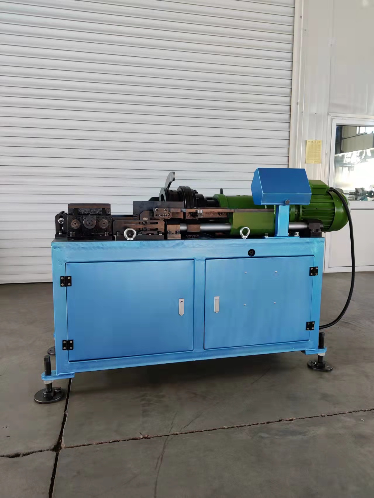
For threaded systems the thread is a design parameter, not a purchasing detail. Parallel thread couplers in this portfolio start at M16.5×2.5 for the smaller bar sizes and extend to larger metric sizes towards the 32–40 mm end of the band, with a 60-degree thread flank angle. Buyers should write the thread designation, the required thread length and the bar-end preparation condition into the enquiry, because two suppliers quoting a coupler for the same nominal bar size may be quoting different thread lengths and different bar-end conditions — and only one of those quotations will fit the design.
Thread length is bounded by the machine, not only by the coupler. Threading machines in this class cover a 16–40 mm rebar range, and maximum threading length is model-dependent: published values of 95 mm and 120 mm appear across the threading-machine specifications reviewed here, and machine operating modes include quick and slow options. Where a design requires a long thread — typically at large-diameter splices in heavy structures — confirm the required thread length against the machine's stated maximum before ordering couplers. Otherwise a correctly manufactured coupler can still be unusable because the bar end cannot be threaded to the designed length.
Two further checks belong in this step. The first is where the bar ends will be prepared: on-site cutting and threading with a thread cutting machine such as the MQ40, a quick-type threading machine such as the 40MO, or an automatic threading machine such as the 40AO represent different answers to different throughput and labour assumptions. The second is whether the design requires an upset end at all; upset forged couplers use the 36S or 50S upsetting machines, which is a different production route from a straight parallel thread and adds a process step to the schedule.
Step 3 — Match the method to the project type
The four documented scenarios — high-rise buildings, airport projects, high-railway stations and large bridges including sea-crossing bridges — differ less in rebar size than in inspection intensity, site access and loading conditions. That is where project type enters the framework.
- High-rise buildings. Reinforcement is dense, splices repeat at every floor, and machinery access is tight. Rolling couplers with on-site threading and an electric torque wrench fit this pattern because one threading machine and one wrench serve the whole 16–40 mm band across the structure. One-touch couplers are the practical option where small-diameter bars in the φ11–16 band appear in the same building.
- Airport projects and high-railway stations. Public infrastructure carries heavy document review. Method selection should follow the evidence chain first: which method's test reports, material certificates and installation records the project's inspector will accept. All three families can be documented; the deciding factor is usually which documentation route is already approved in the project specification.
- Large bridges, including sea-crossing structures. Reinforcement concentrates towards the 32–40 mm end of the band, and loading conditions include fatigue and reverse loading. ISO 15835-1:2018, the requirements part of the series, covers static, fatigue and reverse-loading applications, so bridge specifications normally ask for test evidence aligned with those categories rather than a general product certificate. Alloy steel 40CR couplers are the conventional starting point for these splices.
Step 4 — Check supporting equipment before the method is locked
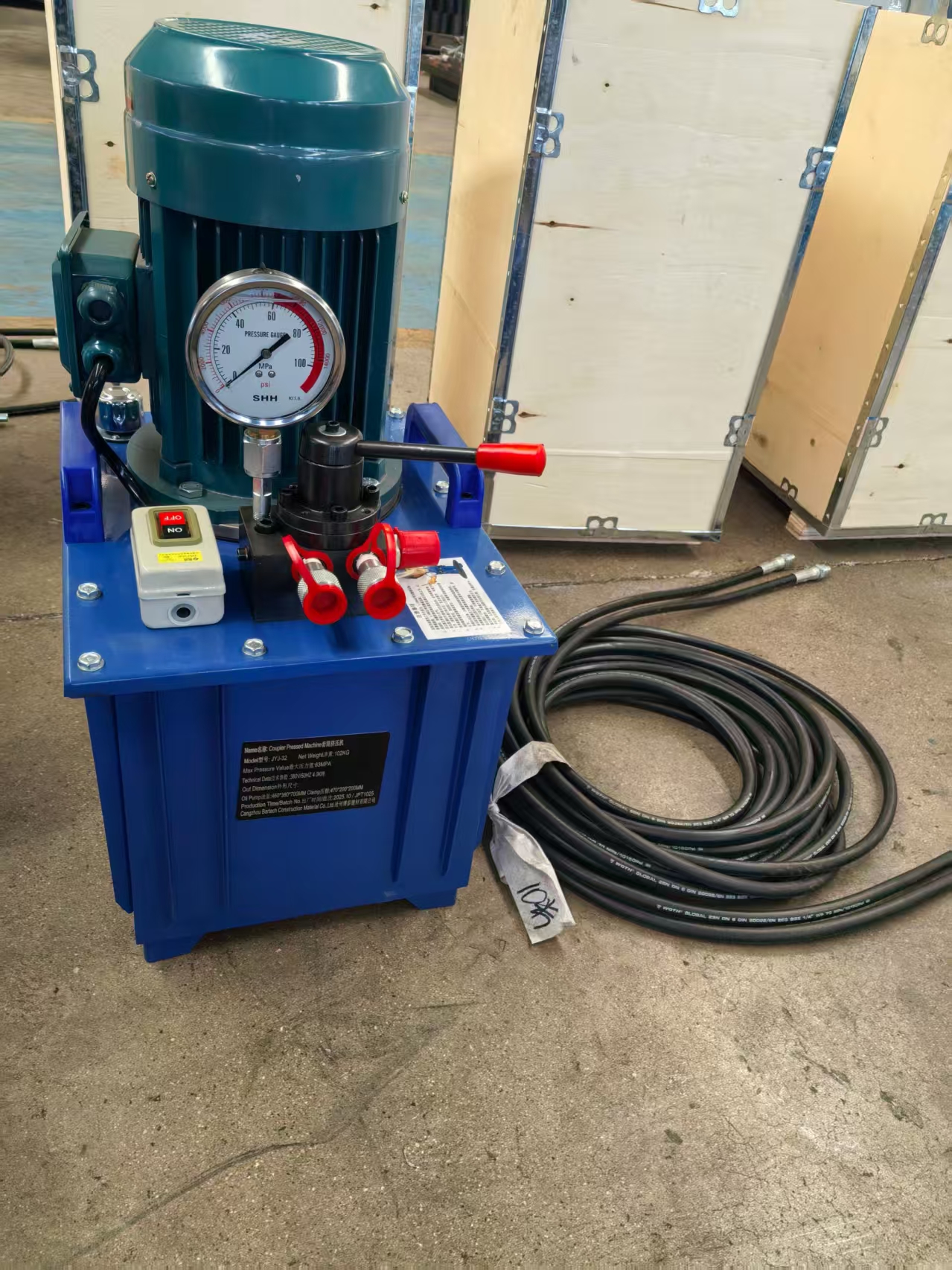
A coupler family is only usable if the site can run the machine that goes with it. The equipment set splits cleanly: the rolling route needs a threading machine plus an electric torque wrench, the pressing route needs a pressing machine, and the one-touch route needs no bar-end threading at all. Omitting equipment from the decision is the most common reason a technically correct coupler becomes a schedule problem.
| Method | Supporting equipment | What the buyer should confirm |
|---|---|---|
| Rolling / parallel thread | Rebar Threading Machine CBT40A or CBT40L (16–40 mm); Rebar Electric Torque Wrench BOC 8-42 and BOC 8-32; Rebar Thread Cutting Machine MQ40 | Machine throughput against the pour sequence; maximum threading length against the designed thread length; power supply; floor space around 1180×670×1150 mm (1300×790×1340 mm on the larger configuration); machine weight around 590 kg for lifting planning; wrench coverage against the largest bar in the schedule |
| Pressing | Rebar Coupler Pressing Machine CBT32 with Q355B couplers, φ16–φ40 | Die-set coverage for every diameter in the schedule; bar-end preparation requirements; the inspection routine applied to each pressed joint |
| Upset forged (where specified) | Rebar Upsetting Machine Auto 36S or 50S, followed by threading | Whether the design requires an upset end at all; the extra cycle time per bar end |
| One-touch | Matching one-touch couplers in alloy steel 40CR, φ11–16 up to φ40 | That the small-diameter band required by the design is actually served; installation procedure for the specific model |
One clarification on the figures above: the dimensions and weight describe the threading-machine specification reviewed for this article, not a universal value for the class. The exact figure should always be taken from the datasheet of the model being quoted, since site layout, crane planning and power supply are usually fixed before the equipment order is placed.
Step 5 — Verify the conformity evidence the framework cannot replace
A method match is a technical fit, not an approval. The ISO 15835 series separates three evidence types that buyers tend to blend into one: ISO 15835-1:2018 specifies requirements for couplers used for mechanical splices of steel reinforcing bars; ISO 15835-2:2018 specifies the test methods applicable to those couplers; ISO 15835-3:2018 specifies rules for certification and self-evaluation. A supplier that holds a certificate but cannot produce test reports against the Part 2 test methods for the exact model and bar size in the schedule is only partially documented.
Market access adds its own layer. Mechanical splices are commonly specified against ISO 15835 alongside ASTM A615 and BS 8110 (Eurocode 2) references, and BS 8597 covers reinforcement coupler requirements and test methods within the UK framework. For customs and trade documentation, rebar couplers are classified under HS code 7307.92.90.
Where certificates are supplied, check the number, scope, issuing body and validity dates rather than the file name. The portfolio referenced in this article holds a CE certificate Nr.SC-PSC-4-2025-12-14 issued under the EU Construction Products Regulation, valid from 2025-12-04 to 2030-12-03, and an ISO 9001 certificate 31623Q10713R1S covering the sales of rebar couplers, rebar connection equipment and related spare parts, valid to 2026-12-21 — a date worth diarising for renewal review before it lapses. Neither document substitutes for a project-specific test report on the coupler model and bar grade actually being installed, and neither resolves the question of which diameter band or thread the project needs.
A project-profile shortlist
Applied as a preference ranking by project profile — not as a claim that one method outperforms another — the framework produces a shortlist that most evaluation teams converge on.
| Project profile | First option to evaluate | Second option | Reasoning |
|---|---|---|---|
| High-rise core and shell, 16–40 mm mix | Rolling (parallel thread), 40CR where a higher strength requirement applies, 45# where the design allows | Pressing (Q355B, φ16–φ40) where on-site threading capacity is limited | One threading machine plus one torque wrench covers the full 16–40 mm band |
| Elements using bars below 16 mm | One-touch (40CR, φ11–16 up to φ40) | Rolling at the lower end of its 16–40 mm band, where the schedule permits | Only the one-touch band reaches below 16 mm in this portfolio |
| Large bridges and heavy transfer structures | Rolling in alloy steel 40CR, with fatigue and reverse-loading test evidence | Upset forged route (36S / 50S plus threading) where the design calls for upset ends | Large-diameter splices carry the highest documentation burden |
| Airports and high-railway stations | The method already approved in the project documentation chain | Any method with a complete Part 2 test record for every model used | Inspection acceptance drives the schedule more than the coupler design does |
| Sites without threading equipment or skilled threading labour | Pressing (Q355B, φ16–φ40) with the CBT32 machine | One-touch for the small-diameter portion of the schedule | No bar-end threading is required on site |
Boundaries: what this framework does not decide
Boundaries matter more than another benefit list, and the honest limits of the framework are the following.
- It matches a method; it does not prove splice strength. Performance depends on test results for the specific coupler model and bar grade, which the framework can only tell a buyer to request. No diameter table replaces that report.
- Compared with traditional lap splicing, couplers are not automatically the cheaper route. In low-stress elements and at small diameters where the lap length fits comfortably inside the section, conventional lapping can remain the simpler and lower-cost solution. A mechanical coupler adds component cost, machine cost and inspection steps that a lightly loaded slab may not justify. The reason to specify one is usually congestion, section size, or a design requirement for load continuity — not a general preference for newer technology.
- Threaded methods depend on bar-end discipline. A correct coupler installed on a poorly cut or incorrectly threaded bar end fails at the interface rather than in the coupler body, which makes bar-end preparation a specification item and not a site detail.
- One-touch couplers are band-limited. As specified in this portfolio they serve a diameter band starting at φ11–16 and extending to φ40; they are not a universal replacement for the rolling or pressing families across an entire project schedule.
- Standard status should be confirmed, not assumed. The ISO catalogue currently lists both the published ISO 15835-1:2018 edition and a related work item. Buyers writing tender documents should verify current status with ISO or with their specifying engineer before citing a standard year in a contract.
Market context: why buyers are standardising on documented methods
The commercial backdrop explains the shift towards formal frameworks. Market research cited for this category places the global rebar coupler market at USD 1.82 billion in 2025, with a projection of USD 3.47 billion by 2034 (Dataintelo). The same research attributes 41.3% of 2025 global revenue to Asia Pacific, which is consistent with the concentration of coupler and connection-equipment manufacturing in Chinese clusters such as Hebei, where the portfolio referenced in this article is produced.
Supply-side capability matters to that context because lead time is a project risk in its own right. The manufacturer referenced here reports monthly capacity of 300,000 pieces, a lead time of 7–30 days depending on quantity, no minimum order quantity on stock couplers, OEM customisation of coupler outer diameter, inner diameter and thread, and a quality-control routine built on material test reports, in-process testing on 10% of production and 100% appearance checking. Documented use includes a Kuwait-based construction enterprise ordering standard rebar couplers at 400,000 pieces per year for outdoor construction, and a Vietnam-based customer applying couplers at 500,000 pieces per year in tall-building and railway-station work.
Future outlook
Three directions are worth tracking through 2026 and 2027. First, documentation will keep tightening: as ISO 15835-3 conformity rules become the reference point in more tenders, buyers will ask for model-level test evidence rather than company-level certificates, which favours suppliers who already hold both and can retrieve them quickly. Second, equipment and coupler supply will be evaluated as one package — a threading machine, a torque wrench and a coupler range quoted together remove the risk of a mismatch discovered only at the first pour. Third, small-diameter quick-connection systems will continue to extend into elements where threading was previously considered uneconomic, which is precisely where the φ11–16 band of one-touch couplers sits.
None of these trends removes the need for the sequence itself — diameter, thread, project type, equipment, documentation. They make the sequence more useful, because each step now has to be evidenced rather than assumed. Buyers who can state which method they selected, for which bar band, with which machine and against which test record are in a considerably stronger position than buyers who simply selected the coupler with the lowest quoted unit price.
FAQ
How do I know which coupler diameter range fits my rebar?
Read the reinforcement schedule first, then compare it with the published ranges: rolling (parallel thread) couplers are listed for 16, 18, 20, 22, 25, 28, 32, 36 and 40 mm bars, pressing couplers cover φ16–φ40, and one-touch couplers cover φ11–16 up to φ40. If any bar in the element is below 16 mm, only the one-touch band covers it within this portfolio, so the diameter check alone can eliminate two of the three options.
What thread specification should appear on a parallel thread coupler enquiry?
The enquiry should state the thread designation starting at M16.5×2.5 for smaller bars and extending to larger metric sizes, the 60-degree thread angle, the required thread length, and the bar-end preparation method. It should also require test evidence referencing the ISO 15835-2 test methods for the specific coupler model and bar grade, because a thread callout without a test reference does not establish splice performance.
Do pressing couplers require threading machines on site?
No. Pressing couplers in carbon steel Q355B cover φ16–φ40 and are installed with the Rebar Coupler Pressing Machine CBT32 without bar-end threading. The trade-off is that die-set coverage must match every diameter in the schedule, and each pressed joint needs its own inspection routine instead of a thread check.
Which equipment is needed for each connection method?
The rolling route uses a Rebar Threading Machine CBT40A or CBT40L for the 16–40 mm range plus a Rebar Electric Torque Wrench BOC 8-42 or BOC 8-32, with optional thread cutting on the MQ40 and threading on the 40MO or 40AO. The pressing route uses the CBT32 machine. The one-touch route uses matching one-touch couplers without bar-end threading. Where upset ends are specified, the 36S or 50S upsetting machines are added ahead of threading.
Which project types are these couplers used in?
The documented application scenarios for this portfolio include construction projects, high-rise buildings, airport projects, high-railway stations and large bridges, including sea-crossing bridges. Recorded project use includes tall-building and railway-station work in Vietnam and outdoor construction supply in Kuwait.
What documents should a buyer check before approving a coupler?
Three groups. First, certificate number, scope, issuing body and validity — for this portfolio, CE certificate Nr.SC-PSC-4-2025-12-14 under the EU Construction Products Regulation, valid 2025-12-04 to 2030-12-03, and ISO 9001 certificate 31623Q10713R1S, valid to 2026-12-21. Second, test reports for the exact coupler model and bar grade, referencing ISO 15835-2 test methods. Third, material test reports for the coupler steel grade. A company certificate alone does not cover the other two.
Reference sources
Market size and regional share: Dataintelo, Rebar Coupler Market Research Report 2034 (cited figures: USD 1.82 billion in 2025; USD 3.47 billion by 2034; Asia Pacific 41.3% of 2025 revenue). Standards: ISO 15835-1:2018, ISO 15835-2:2018 and ISO 15835-3:2018 (International Organization for Standardization); BS 8597 (British Standards Institution); ASTM A615 and BS 8110 / Eurocode 2 as commonly referenced market standards. Trade classification: HS 7307.92.90 (Harmonized Tariff Schedule, US International Trade Commission). Product, equipment, capacity, certification and case data: Cangzhou Bartech Construction Material Co., Ltd. (www.chinabartech.cn).
Have Questions or Need More Details?
Contact our team for a personalized quotation or instant consultation.
Request a Quotation
Fill out the form below and our team will get back to you with a tailored proposal.
WhatsApp Direct Chat
Prefer to chat in real-time? Message us on WhatsApp for instant assistance & quick answers.
- Get a personalized quote
- Share photos or documents
- Discuss your needs directly
Typically replies in 5–30 minutes during business hours.