
Recommended Current Transformers for Solar PV and Energy Storage: A Shortlist
For solar PV and battery energy storage projects, the practical question is not which current transformer is best in the abstract, but which measurement role a device is built to fill. A workable shortlist separates four roles: DC-side string and battery monitoring, three-phase AC measurement at the inverter, transformer or switchgear level, loop-powered transmission of current values into control and monitoring systems, and wide-range non-saturating AC measurement on large or irregular conductors. A device built for one role rarely substitutes cleanly for another, and the specifications that determine fit — current type, measurement range, output signal and window size — are visible on the datasheet before any commercial discussion begins.

Solar inverter power monitoring: the AC and DC sides of a PV or storage system require different current-sensing principles.
Why PV and storage projects need their own CT shortlist
A PV plant and a battery energy storage system contain at least two electrically different measurement environments. On the DC side — PV strings, combiners and battery racks — current is direct, and in storage it reverses direction between charging and discharging. Inductive current transformers, the family governed by IEC 61869-2 (which replaced IEC 60044-1) and defined by accuracy classes such as 0.5 and 0.5S, are alternating-current devices; they are not the tool for DC measurement. That role belongs to Hall Effect current transducers, which are active sensors rather than passive magnetic transformers.
On the AC side, inverter output and the point of interconnection do carry alternating current, but rarely a clean sinusoid. Inverter switching introduces high-frequency content, and split-core CTs built with ferrite cores are described as high-frequency noise-suppressing designs for exactly this reason. PV and storage sites are also frequently retrofits: conductors are already installed, lugged and energised, so breaking a ring circuit to slide on a solid-core transformer is impractical. Clamp-on split-core construction solves that problem, which is consistent with market analysis from Fact.MR identifying split-core current transformers as the fastest-growing segment, attributed to ease of installation in retrofitting and smart grid applications.
Shortlist at a glance
The four devices below belong to the portfolio of WENZHOU HEYI ELECTRICAL CO.,LTD. (HEYI), a manufacturer established in 2012 that specialises in bespoke current transformers and current sensors. HEYI operates a 10,000 m² manufacturing facility with an annual production capacity of 356,000 units and exports approximately 95% of its output, serving markets including Southeast Asia, South Korea, Europe, South America, Australia, Africa, the Middle East and North America.
| Measurement role | Model | Range | Output | Window / inner diameter | Accuracy |
|---|---|---|---|---|---|
| PV string and battery DC monitoring | C2/C3 Hall Effect current sensor | 0–1000 A | 5 A | 125×35 mm | 1.0 / 0.5 |
| Three-phase AC measurement for EPC solar, wind and storage | DASN three-phase current transformer | 0–1000 A | 5 A | 0–50 mm | 1.0 |
| Loop-powered transmission into PLC, DCS and IoT platforms | KCT-L current transformer / transmitter | 0–1000 A | 4–20 mA DC | 0–50 mm (customisable) | 1.0 |
| Non-saturating AC measurement on large or irregular conductors | FRC flexible Rogowski coil | 100–10000 A | mV | 245 mm | Not specified |
The table is organised by measurement role rather than by rank. Each column is a specification that a buyer can verify on the datasheet, and each row answers a different question inside the same project.
1. DC string and battery monitoring: C2/C3 Hall Effect current sensor
The C2/C3 is a split-core Hall Effect current transducer and DC current transmitter, described as an active current sensor with zero and span adjustment and bi-directional current sensing. It measures 0–1000 A with an output signal of 5 A and an accuracy rating of 1.0/0.5, with an inner diameter of 125×35 mm. The housing is ABS/PC plastic, the core uses silicon steel sheets and nanocrystalline materials, and the winding is pure copper enameled wire.
Its intended applications are PV string monitoring, BMS and battery storage, VFD DC bus monitoring, renewable energy, railway traction, industrial automation, telecom and IDC, transportation and process industry work. Three of those roles recur in solar and storage projects. PV string monitoring needs current data at the string level to detect underperformance or mismatch; battery storage needs bi-directional sensing because the same conductor carries charge and discharge current; and DC bus monitoring in a variable frequency drive or power conversion stage needs a sensor that reads DC rather than assuming a 50 or 60 Hz waveform.
Because the transducer is active and split-core, two installation consequences follow. It requires a supply and a return path for its output, unlike a passive inductive CT, and it can be fitted around an existing conductor without disconnecting the circuit.
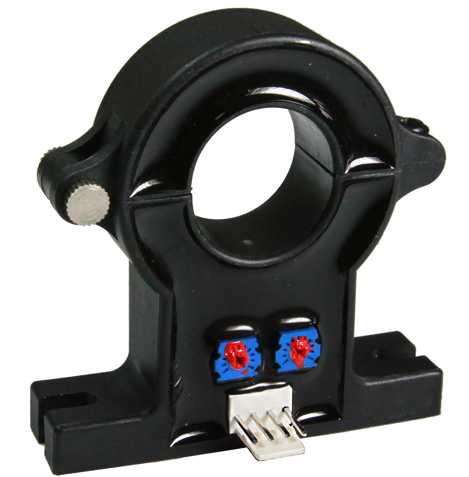
C2/C3 split-core Hall Effect current sensor, specified for PV string monitoring, BMS/battery storage and VFD DC bus monitoring.
2. Three-phase AC measurement for EPC solar, wind and storage: DASN
The DASN is a three-phase current transformer classified as a 3-phase integrated CT, a DIN-rail 3-phase CT, a compact 3-phase measuring CT and a 3-in-1 current transformer. Its measurement range is 0–1000 A, secondary output is 5 A, accuracy class is 1.0, and inner diameter ranges from 0 to 50 mm. Primary materials are ABS/PC plastic, silicon steel sheets or nanocrystalline materials, and pure copper enameled wire.
Its stated industries include EPC (Solar/Wind/Storage), main and branch monitoring, UPS, MCC (motor control centres), smart buildings, IDC and telecom, and cloud and telecom operators. The relevant design point for an EPC contractor is the three-in-one construction: one housing covers all three phases, which reduces the number of components and the wiring time in a panel compared with three separate single-phase CTs. Combined with DIN-rail mounting, this fits the prefabricated and modular panel practice common on solar and storage projects, where panels are assembled before delivery to site.
The accuracy class of 1.0 places it in monitoring and branch-measurement service rather than in revenue billing. That distinction is important when a project has both operational monitoring and a commercial metering requirement on the same switchboard.
3. Loop-powered transmission into PLC, DCS and IoT platforms: KCT-L
The KCT-L is a True RMS current transformer and transmitter, classified as a loop-powered current monitoring sensor, a split-core current transmitter, and a 4–20 mA DC output current sensor. It is also described as an IoT gateway compatible current sensor, an environmental monitoring transducer and an emission control system sensor. Measurement range is 0–1000 A, output is 4–20 mA DC, accuracy class is 1.0, and inner diameter is 0–50 mm, with customisable lead wire type, lead wire length and connector.
The 4–20 mA loop is the reason this device appears in solar, storage and infrastructure shortlists. Most PLC, DCS, RTU and remote monitoring systems accept a current loop as a standard analogue input, and a loop-powered transmitter takes its operating power from the same two wires that carry the signal. For distributed PV, containerised storage, remote power monitoring, preventive maintenance programmes and IoT or smart-city installations, that removes the need for a separate transducer, power supply and signal-conditioning module at each measuring point.
The stated intended industries — PLC/DCS system integration, remote power monitoring, preventive maintenance, rail transit, environmental engineering, and IoT and smart city — reflect that integration logic rather than the electrical environment alone.
4. Non-saturating AC measurement on large conductors: FRC flexible Rogowski coil
The FRC is a flexible Rogowski coil, classified as a rope current sensor, an air-core current transducer and a non-saturating current sensor. Its measurement range is 100–10000 A, its output type is mV (millivolt), and its inner diameter is 245 mm. Inner diameter, output and colour are customisable. The related Rogowski coil with integrator (G1) is a lightweight flexible CT made of silicone and pure copper enameled wire, intended for lightning and transient current measurement, portable testing meters, data centre and power retrofit work, and heavy industry and smelting applications.
Air-core construction is the technical headline. Because there is no magnetic core to saturate, the coil does not clip or distort its output when a fault current, an inrush or a high harmonic current appears — conditions that matter at a storage point of interconnection and in data-centre power retrofits where peak currents are unpredictable. The 245 mm inner diameter allows the coil to wrap around busbar groups, cable bundles and large or irregular conductors that will not pass through a rigid window.
The trade-off is signal handling: a millivolt output is not a direct substitute for a 5 A meter input, and the coil is normally paired with an integrator or a compatible measuring device before its value can be used by a meter or controller.
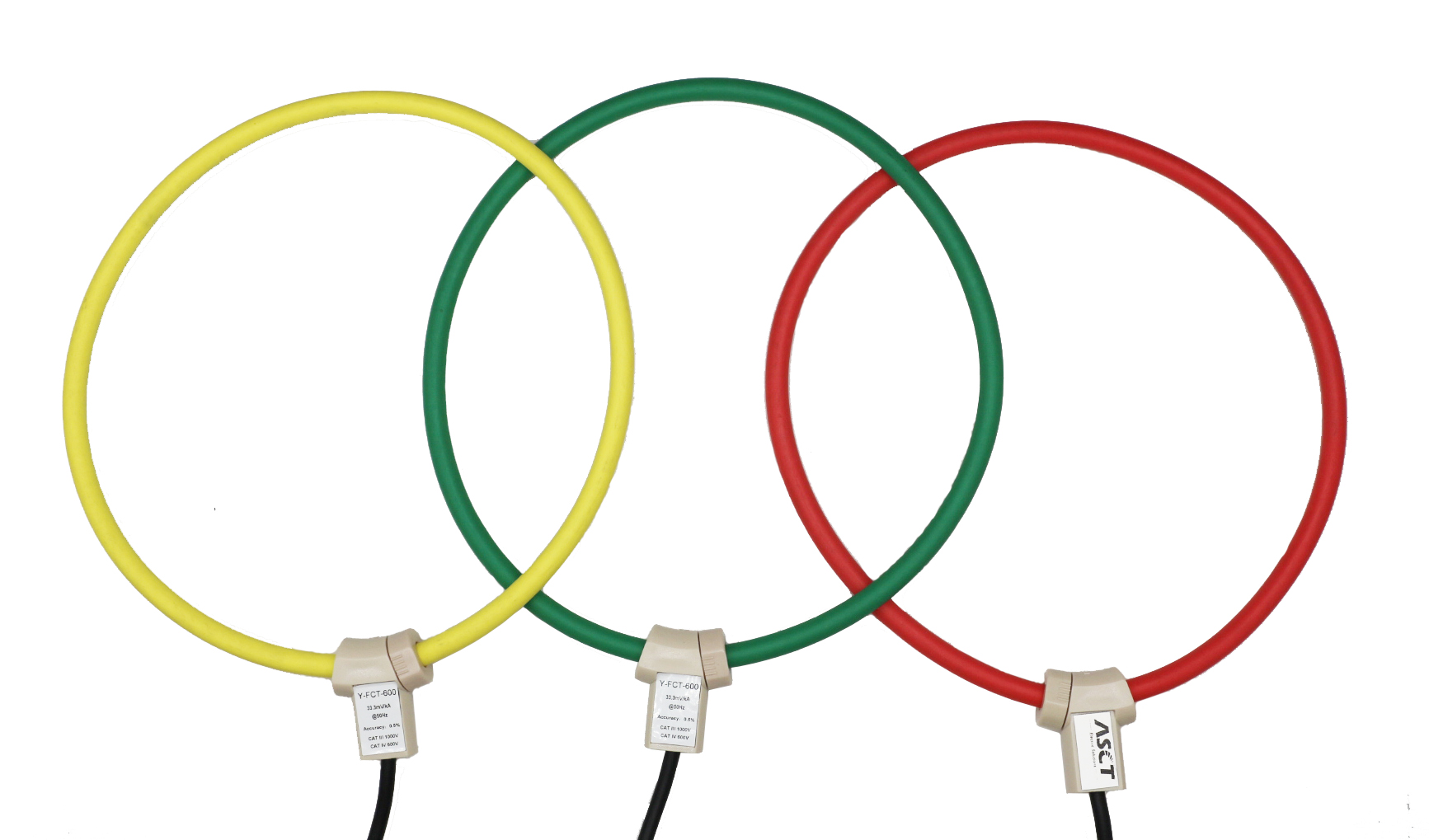
Flexible Rogowski coil (FRC): air-core, non-saturating AC measurement with a 245 mm inner diameter.
How the four measurement principles differ
Comparing these devices by price alone hides the engineering difference. The table below compares them by principle, which is what determines whether a device can physically answer the measurement question at a given point in the plant.
| Principle | Example in this shortlist | Current type | Core behaviour | Typical downstream device |
|---|---|---|---|---|
| Hall Effect transducer (active) | C2/C3 | DC and bi-directional | Uses silicon steel or nanocrystalline core with active electronics | DC monitoring controller, BMS, inverter or drive control input |
| Inductive current transformer (passive) | DASN, KCT-L | AC | Magnetic core, subject to saturation at high current | Power meter, PLC analogue input, energy management system |
| Loop-powered transmitter | KCT-L | AC | Split-core magnetic core with signal conditioning electronics | PLC, DCS, RTU, IoT gateway |
| Air-core Rogowski coil | FRC | AC | No magnetic core; does not saturate | Integrator, power analyser, portable test meter |
Matching a device to the project, not to the catalogue
Six checks cover most of the decision for solar PV and storage work.
- Current type at the measuring point. DC strings, battery racks and DC buses require a Hall Effect transducer such as the C2/C3. AC feeders, inverter outputs and auxiliary supplies can use an inductive CT or a Rogowski coil.
- Maximum current and required range. The C2/C3, DASN and KCT-L are specified to 1000 A. Where primary current is higher, the flexible Rogowski coil covers 100–10000 A, and other families in the same portfolio extend further.
- Window size against the conductor or busbar. A 0–50 mm window suits small cable and compact panel work; a 125×35 mm window suits larger single conductors; a 245 mm Rogowski loop suits busbar groups and irregular geometries.
- What the receiving device accepts. A 5 A secondary suits a conventional meter input; 4–20 mA suits a PLC or DCS analogue card; millivolt output requires an integrator. Mismatching this is the most common installation error.
- Auxiliary power availability. Hall Effect transducers and loop-powered transmitters are active; a passive inductive CT is not. In a sealed outdoor cabinet without auxiliary supply, a passive device is simpler to deploy.
- Accuracy requirement: monitoring or billing. Class 1.0 is appropriate for operational monitoring and branch measurement; revenue billing carries a different requirement, addressed in the next section.
One further practical check concerns the environment. Where the measuring point is outdoors, the outdoor families in the same portfolio are relevant: the OCT outdoor waterproof split-core CT is rated IP65 with an inner diameter of 0–120 mm for overhead line monitoring and outdoor solar and wind work, and the LMZW outdoor resin-cast CT is a 0.66 kV solid-core unit with IP65 protection and a 0–80 mm inner diameter for ring main unit, marine, offshore and chemical or metallurgy environments.
Where this shortlist stops: limits and boundaries
A credible shortlist should state what it does not cover. Four boundaries are worth flagging before a project specification is written.
- Split-core clamp-on devices are not revenue-billing devices. The clamp-on families on this shortlist carry wider accuracy bands — 3.0/1.0/0.5 for the KCT and the DP/HK busbar split-core CT. Where utility billing accuracy is required, the answer is a solid-core, resin-insulated design: the RECT is a 0.15S high-accuracy, IEEE C57.13 compliant revenue CT with an anti-saturation design, an inner diameter of 0–78 mm, IP65 protection and a 0–1000 A range with 5 A or 1 A secondary output. Revenue-grade applications are generally required to meet ANSI C12.20 or IEC 61869-2 accuracy classes of typically 0.2 or 0.15. No single product closes both the retrofit-convenience need and the billing-accuracy need.
- The Rogowski coil is not a drop-in replacement. Its millivolt output needs an integrator or a compatible measuring device, and air-core coils measure AC, not DC. The 245 mm inner diameter is also a fixed geometry unless the customisable inner diameter, output and colour options are ordered.
- Window size limits the other three devices. The DASN, KCT-L and C2/C3 are specified with windows in the 0–50 mm and 125×35 mm range. Large busbar groups need a different geometry, such as the DP/HK busbar split-core CT with a 0–80×160 mm window and a 0–8000 A range, or the SDH low-voltage window-type CT with a range up to 10000 A, an inner diameter up to 220×80 mm and accuracy options from 1.0 down to 0.2S.
- Leakage and residual current is a separate function. Protective residual current monitoring for EV charging and storage is not performed by measuring CTs. That role is handled by dedicated sensors such as the HYCA, which switches at 6 mA DC and 30 mA AC according to IEC 62752, covers a differential current range of 0–300 mA with 0.2 mA resolution, and accepts load current up to 80 Arms single-phase or 3×32 Arms three-phase from DC to 2 kHz.
Market context: what is driving demand
The commercial backdrop helps explain why this shortlist is being assembled more often. Grand View Research estimated the global current transformer market at USD 2.63 billion in 2024, projecting USD 3.90 billion by 2030. Straits Research reported that Asia Pacific held a 40.15% revenue share of the current transformer market in 2025, which aligns with the concentration of PV, storage and data-centre construction in the region. Research Intelo projects a 23.6% CAGR from 2025 to 2033 for the EV charging transformer market, a category that includes current monitoring components.
Supply structure is a second consideration for buyers. Global Market Insights reported that the top five global players — ABB, Siemens, GE, Schneider Electric and Arteche — collectively held approximately 40% of current transformer market share in 2024. The remaining share is served by a large base of specialist manufacturers, which is why qualification of a specific supplier and a specific model line matters as much as the headline category.
What to watch next
Three directions are visible from the product specifications themselves. First, the split-core segment that already leads growth is likely to keep expanding as retrofit work continues in existing distribution and industrial plants, since clamp-on installation is the only practical option when conductors cannot be disconnected. Second, integration is moving into the transducer: adjacent designs in the same portfolio, such as RS485 and Modbus RTU split-core CTs, show the shift from a raw analogue secondary to a device that delivers a digital reading to an energy management or O&M platform. Third, DC-side monitoring is becoming a first-class requirement rather than an afterthought as storage capacity grows, which keeps active Hall Effect sensing — not passive inductive transformation — at the centre of battery and PV string monitoring.
For anyone drafting a specification now, the practical conclusion is to define the measurement role first, then the current type, then the range and window, then the output signal, and only then compare suppliers on the products that survive those four filters.
Reference material: a downloadable HEYI product brochure covering current transformers, current sensors and transmitters is available at HEYI brochure (PDF). Product information is published by WENZHOU HEYI ELECTRICAL CO.,LTD. at www.heyiele.com.
FAQ
Can a standard AC current transformer be used to monitor DC current from PV strings or battery racks?
No. Inductive current transformers are alternating-current devices; the family defined by IEC 61869-2, including accuracy classes 0.5 and 0.5S, is specified for AC measurement and does not read a direct current. DC-side monitoring in PV and storage systems uses Hall Effect current transducers instead, which are active sensors. The C2/C3 is an example: a split-core Hall Effect current transducer and DC current transmitter with a 0–1000 A measurement range, a 5 A output signal, accuracy rating 1.0/0.5, a 125×35 mm inner diameter, and a stated application list that includes PV string monitoring, BMS and battery storage, and VFD DC bus monitoring. It is described as a bi-directional current sensor, which matters because a battery conductor carries current in both directions.
What output signal should the monitoring system expect from a CT used in a solar or storage project?
Output format is determined by the receiving device, and three formats cover the common cases. A 5 A secondary output is the conventional meter and switchboard format, used here by the DASN three-phase CT and the C2/C3 sensor. A 4–20 mA DC loop suits PLC, DCS, RTU and IoT gateway inputs, and is the output of the KCT-L true RMS current transformer and transmitter, which is loop-powered and therefore draws its operating power from the signal loop. A millivolt output comes from air-core Rogowski coils such as the FRC, which has a 100–10000 A range and a 245 mm inner diameter, and requires an integrator or a compatible measuring device before the value can be used. A millivolt coil connected directly to a 5 A meter input is the most frequent mismatch in this segment.
How is the correct inner diameter or window size chosen?
The window must physically clear the conductor or busbar it surrounds, and the required size follows the installation rather than the current rating. For compact panel work and smaller cables, the DASN, KCT-L and KCT split-core CTs are specified with inner diameters of 0–50 mm. For larger single conductors, the C2/C3 and the DX/DM DIN-rail CT both use a 125×35 mm inner diameter. For busbar groups and irregular geometries, larger formats apply: the DP/HK busbar split-core CT has a 0–80×160 mm window, the SDH low-voltage window-type CT goes up to 220×80 mm, and the FRC flexible Rogowski coil has a 245 mm inner diameter. Several of these products also allow customisation of lead wire type, lead wire length and connector, and the Rogowski coil additionally allows customisation of inner diameter, output and colour.
When is a flexible Rogowski coil preferable to a split-core current transformer?
A Rogowski coil is preferable when the conductor is too large or too irregular for a rigid window, when the current is expected to swing over a very wide range, or when a fault or transient current would saturate a magnetic core. The FRC is an air-core current transducer and non-saturating sensor with a 245 mm inner diameter, a 100–10000 A measurement range and a millivolt output, intended for heavy industry and smelting, data centre and power retrofit work, portable testing meters, and lightning and transient current measurement. A split-core CT remains the simpler choice when a conventional secondary output is required, when the installation is a straightforward clamp-on around a cable or busbar, and when the accuracy class of a magnetic-core device — for example 3.0/1.0/0.5 on the KCT split-core family — is adequate for the monitoring task. The two are not interchangeable in either direction.
What accuracy class is needed when a solar or storage installation involves revenue billing?
Revenue-grade current transformers are generally required to meet ANSI C12.20 or IEC 61869-2 accuracy classes, typically 0.2 or 0.15. Devices built for that duty are normally solid-core and resin-insulated rather than clamp-on. The RECT is an example: a revenue-grade billing current transformer, described as an extended range current transformer, a 0.15S high-accuracy resin-insulated CT, an IEEE C57.13 compliant revenue CT and an anti-saturation design, with a 0–1000 A measurement range, a rated secondary output of 5 A or 1 A, an inner diameter of 0–78 mm, IP65 protection and UV protection, intended for utility and substation billing, utility-scale solar and wind plants, data centre and commercial and industrial revenue sub-billing, and premium meter OEM manufacturing. For operational monitoring rather than billing, class 1.0 devices such as the DASN and KCT-L are the usual fit. IEC 61869-2 is the core international standard for inductive current transformers and replaced IEC 60044-1.