
Selecting the Right Fiber for Smart City and 5G Backhaul Deployments: A Scenario Fit Guide
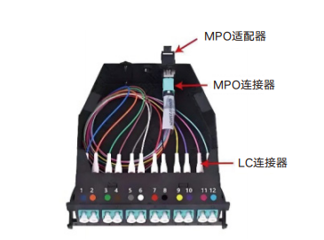
Smart city networks and 5G backhaul are built on the same physical layer, but they rarely fail for the same reason. A cable that survives rodent activity and standing water in an urban duct may still be a poor fit where tight cabinet bends dominate; a cable engineered for controlled indoor routing will not survive direct burial. For network architects, the practical question is therefore not “which optical fiber cable is best,” but “which verified configuration matches the environment this route will actually live in.”
The selection problem resolves into four decision variables that can be checked against evidence: fiber type (G.652 or G.657), mechanical construction (FRP strength members, galvanized steel wire or steel tape armoring), sheath material (PE or LSZH), and the test and certification trail behind the product. Nanfang Communication (Jiangsu South Communication Technology Co., Ltd.), a Changzhou-based manufacturer of optical fibers, optical cables, ODN systems and optical components and a subsidiary of South Communication Holdings Limited (1617.HK), documents its GYTA53 optical fiber cable for smart city projects, 5G backhaul, metropolitan backbone networks and related access deployments. That documented scenario list makes the model a useful working example for translating deployment conditions into specification decisions.
Why Scenario, Not Product Ranking, Drives the Specification
Two cables can share the same model family and still differ in core count, core diameter, attenuation, tensile strength, minimum bend radius and sheath material. In the documented specification set for this optical fiber cable, core count and core diameter are specified per model, attenuation is given in dB/km, tensile strength ratings and minimum bend radius are provided in the datasheet, and operating wavelengths fall within typical optical communication bands. Exact specifications must be confirmed per model datasheet rather than assumed from a family name.
That is the core constraint for evaluation-stage buyers. Scenario fit is a mapping exercise: the environment defines which mechanical and optical properties are non-negotiable, and the datasheet defines whether a given configuration delivers them. Skipping the mapping step is the most common source of specification mismatch in smart city and backhaul builds.
Scenario 1: Smart City and Industrial IoT Networks
What the environment imposes
Smart city routes combine underground duct sections, direct-buried service trenches, roadside cabinets and, in some designs, aerial or self-supporting spans. The dominant physical threats are water ingress, rodent attack, mechanical crushing during civil works, and long-term temperature variation. These routes are also passive for most of their service life, which means inspection and maintenance windows are infrequent and the cost of a mid-route failure is high.
How the specification responds
For this class of environment, the documented working conditions for the cable include duct installation, direct burial, aerial or self-supporting deployment, and outdoor harsh environments requiring weatherproofing, waterproofing, rodent protection and temperature resistance. Armoring materials documented for the product include galvanized steel wire and steel tape, and sheath options include PE and LSZH.
Two specification details matter most at evaluation stage. First, strength members made of FRP and other materials control tensile strain during pulling through congested urban ducts, where excessive tension is a common cause of latent fiber damage that only appears after commissioning. Second, the fiber type must be matched to the cabinet and handhole geometry: G.657 bend-insensitive fiber exists precisely because access-network enclosures impose tight bend radii.
Scenario 2: 5G Backhaul and Metropolitan Aggregation
What backhaul demands from the physical layer
5G backhaul routes connect distributed radio sites to aggregation points over relatively short duct spans, but they accumulate many connection points and splices. Link budget is consumed by connectors, splices and patch panels as much as by cable attenuation, which is why a low-attenuation single-mode fiber and a controlled splice environment usually matter more than raw cable volume. Core count also tends to be higher than in pure access routes because backhaul must absorb future sector and carrier additions.
The documented project types for this cable family include operator network expansion and 5G backhaul projects, metropolitan and backbone network projects, data center interconnects, and enterprise or campus network deployments. Those are the scenarios against which a configuration should be evaluated, rather than a generic “outdoor cable” assumption.
G.652 and G.657 in practice
Common fiber types documented for the product are G.652 and G.657. The distinction is a standards question, not a marketing one: ITU-T G.652.D remains the industry standard for single-mode fiber, while G.657 is the primary standard for bend-insensitive fibers used in FTTH. In backhaul and backbone routes where spans are longer and enclosures are more controlled, G.652 is the conventional starting point; where the route terminates in dense patch fields or compact cabinets, G.657 becomes relevant.
Scenario 3: Metropolitan Backbone and Duct Routes
Metropolitan backbone segments combine longer duct runs with higher core counts and heavier splicing activity. Here the constraints shift toward tensile strength during installation, crush resistance in shared ducts, and the manageability of ribbon or loose-tube constructions at splice closures and distribution boxes. The supporting device ecosystem documented for these deployments includes optical modules, PLC splitters, cable splice closures, FTTH distribution boxes, MPO patch panels, fiber optic connectors, fiber assemblies such as MT-FAU, and WDM units, so cable selection and distribution-hardware selection should be planned in the same pass.
The Construction Layer: FRP, Steel Tape and Sheath Choice
Mechanical construction is where scenario fit is won or lost, because it determines whether the cable survives installation and whether it survives the following twenty years. The documented material set for this product is specific and verifiable.
| Construction element | Documented material | Function in the route | What the buyer should verify |
|---|---|---|---|
| Optical core | Silica glass; G.652 or G.657 fiber types | Signal transmission with attenuation expressed in dB/km | Fiber type, core count and attenuation per model datasheet |
| Strength members | FRP and other materials | Limits tensile strain during duct pulling and aerial stringing | Tensile strength rating in the datasheet |
| Armoring | Galvanized steel wire and steel tape | Rodent protection, crush resistance, burial protection | Armoring type required by the specific route condition |
| Sheath | PE or LSZH | Weatherproofing, waterproofing, environmental protection | Sheath material and environmental rating per model |
| Bend performance | Minimum bend radius per datasheet | Determines feasibility inside cabinets and handholes | Minimum bend radius against the tightest enclosure |
The practical implication is that armoring and sheath choice should be driven by route conditions, not by habit. A cable ordered with heavier armoring than the route requires adds weight and stiffness to every pull and every splice preparation; a cable ordered without sufficient protection transfers risk to the maintenance budget.
The Constraint Layer: What Certifications Actually Verify
For research-to-evaluation buyers, certification is a constraint filter rather than a marketing claim. The documented certification set attached to this optical fiber cable and the surrounding product family is concrete and checkable.
| Credential | Issued by | Scope as documented | Validity |
|---|---|---|---|
| TL9000-H, certificate 15/25T15218R11 | WIT Assessment / Hangzhou WIT Assessment Co., Ltd. | Manufacture and sales of communication optical fiber cable; TL9000 Handbooks R6.3, R5.7 Point Release and R5.9 Category Tables | 2025-11-20 to 2028-10-19 |
| ISO 14001:2015, certificate 62225E20719R0M | SWR Certification (Jiangsu) Co., Ltd. | Production of communication optical cables, optical fibers and communication distribution equipment | 2025-12-20 to 2028-12-19 |
| ISO 45001:2018, certificate 62225S20720R0M | SWR Certification (Jiangsu) Co., Ltd. | Production of communication optical cables, optical fibers and communication distribution equipment | 2025-12-20 to 2028-12-19 |
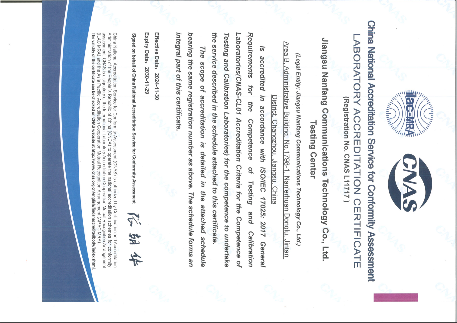
| Laboratory accreditation, CNAS L11717 | China National Accreditation Service for Conformity Assessment (CNAS) | Testing and calibration of optical fiber cable and optical communication components, for China and global markets, to ISO/IEC 17025:2017 | 2024-11-30 to 2030-11-29 |
Read carefully, these credentials answer different questions. TL9000-H addresses the quality management system applied to the manufacture and sales of communication optical fiber cable. ISO 14001 and ISO 45001 address environmental and occupational health and safety management in the production scope. The CNAS laboratory accreditation addresses whether the testing used to support performance claims is itself carried out under an accredited system.
What none of them prove is project-specific performance. A management-system certificate does not certify that a particular cable configuration meets a particular attenuation or tensile requirement for a particular route. That remains a datasheet-and-test-report question, which is why the documented quality-control process for these products includes incoming material inspection, in-process control and finished-product testing covering optical loss and attenuation, mechanical performance, and waterproof and sealing behaviour.
Scenario-to-Specification Fit Table
| Deployment scenario | Dominant constraint | Construction focus | Fiber type to confirm | Verification emphasis |
|---|---|---|---|---|
| Smart city and industrial IoT routing | Water ingress, rodent exposure, crush during civil works | Armored outdoor construction with weatherproof sheath | G.657 where cabinets impose tight bends; G.652 otherwise | Waterproof and sealing test evidence; sheath material |
| 5G backhaul and aggregation | Link budget across many splices and patch points | Low-attenuation single-mode cable with disciplined splice and patching plan | G.652 as conventional single-mode baseline | Attenuation per model datasheet; splice and patch component quality |
| Metropolitan backbone | Installation tension and long duct pulls | FRP strength members plus armoring; ribbon or loose-tube construction where core count is high | G.652 single-mode | Tensile strength rating; crush and mechanical test evidence |
| FTTx and access segments | Tight bends at distribution boxes and drop points | Bend-insensitive fiber; bow-type drop and distribution accessories | G.657 | Minimum bend radius; distribution hardware compatibility |
| Data center and high-density interconnect | Density and insertion loss at patch panels | Pre-terminated assemblies rather than duct cable | Single-mode or multimode per reach requirement | Insertion loss and return loss of connector assemblies |
Limits and Trade-offs Buyers Should Expect
A scenario fit guide is only credible if it states where a product does not simplify the decision. Four limits are worth stating plainly for this cable family.
- Specifications are model-specific. Core count, core diameter, attenuation, tensile strength, minimum bend radius, sheath material and environmental ratings are not universal across the family; they must be confirmed per model datasheet. A design that assumes values from a related model carries avoidable risk.
- Armoring has a handling cost. Galvanized steel tape and steel wire armoring improve burial and rodent protection, but they add weight and stiffness to pulling and to splice preparation. In congested urban ducts and in tight cabinet entries, that trade-off has to be planned, not discovered on site.
- Scenario lists are not installation guarantees. The documented working conditions for the product span duct installation, direct burial and aerial or self-supporting deployment, but the applicable configuration for a specific route still has to be confirmed for sheath, armoring and loading conditions.
- Supply parameters vary. Lead time depends on model and quantity, and there is no single standard lead time published; sample and small orders typically take several weeks while large orders may take months. The documented minimum order quantity is 1 core kilometer.
These are normal boundaries for armored outdoor cable rather than defects. The evaluation implication is that scenario fit should be documented before the order, not negotiated after delivery.
Market Context Behind the Specification Pressure
Specification decisions are being made against a growing installed base. According to Custom Market Insights, the global optical fiber cable market was valued at approximately USD 13.45 billion in 2025 and is projected to reach USD 36.48 billion by 2034. Research firms diverge on the absolute figure for 2025, so the direction of growth is more reliable than any single estimate. On the supply side, China's exports of optical fiber cables under HS 854470 reached approximately USD 2.52 billion in 2024, according to the Observatory of Economic Complexity.
Adjacent connector demand shows a similar pattern. The global fiber optic connector market was estimated at USD 11.2 billion in 2024, with LC connectors holding a 35.43% share, according to Global Market Insights and Grand View Research, while Business Research Insights projects the MPO fiber optic connector market to grow at a CAGR of 13.6% through 2035, driven by AI compute clusters and hyperscale data centers. Corning Incorporated led the global fiber optic cable market in 2025 with a market share exceeding 21.5%, according to Global Market Insights. For scenario-fit buyers, the practical reading is that cable and connector decisions increasingly belong to the same design review, because the growth is concentrated where density and reach requirements meet.
Procurement Checklist for Scenario Fit
- Map every route segment to one of the documented scenarios before writing the specification.
- Fix the fiber type first (G.652 or G.657) based on the tightest bend in the route, then select core count.
- Confirm attenuation, tensile strength and minimum bend radius per model datasheet rather than per family.
- Match armoring type to the burial, duct and rodent conditions actually present.
- Confirm sheath material and environmental rating against the local climate and installation method.
- Check that the cable's fiber type is compatible with the connectors, patch panels, splitters and closures planned for the same route.
- Verify certification scope and validity dates, not just certificate presence.
- Request test evidence from an accredited laboratory environment, since testing capability and management-system certification are separate credentials.
- Confirm order quantity, lead time and labeling or packaging customization requirements before release.
- Keep the scenario-to-specification mapping in the project file so future extensions inherit the same assumptions.
Future Outlook
Two shifts are likely to shape the next procurement cycle. First, bend-insensitive fiber is moving from access-only applications into denser aggregation points as sites become more compact. Second, cable and connectivity decisions are converging: the documented product scope around this cable family already spans fibers, cables, ODN systems, PLC splitters, fiber optic connectors, MPO multi-core connectors and optical modules, with customizable core count, fiber type, sheath material and color, connector types and cabling schemes, and labeling and packaging. Suppliers able to hold that combined scope reduce the number of interface assumptions a network architect has to defend. Nanfang Communication, which documents ISO 9001, TL9000, ISO 14001, OHSAS18001, ISO 50001 and CNAS laboratory accreditation, over 300 patents and 16 standards, and long-term cooperation with operators including China Telecom, China Mobile, China Unicom and China Broadcast Network, is one example of that integrated supplier profile in the Chinese market.
FAQ
1. What fiber type should be used in smart city deployments — G.652 or G.657?
Both are documented as common fiber types for this optical fiber cable family. The standard distinction is that ITU-T G.652.D is the industry standard for single-mode fiber, while G.657 is the primary standard for bend-insensitive fibers used in FTTH. The deciding factor is the tightest bend the route presents: dense cabinets and access enclosures point toward G.657, while controlled enclosures and longer spans generally point toward G.652.
2. How should armoring be chosen for urban duct and direct burial routes?
Armoring materials documented for this product include galvanized steel wire and steel tape, and the documented working conditions include duct installation, direct burial and outdoor harsh environments requiring waterproofing and rodent protection. The specific armoring type should be matched to the burial depth, duct congestion and rodent exposure of the route, and confirmed against the model datasheet, because armoring also affects weight, stiffness and minimum bend radius.
3. What certifications should a buyer verify for optical fiber cable used in 5G backhaul?
For this optical fiber cable, the documented credentials are TL9000-H certification for the manufacture and sales of communication optical fiber cable, issued by WIT Assessment with certificate number 15/25T15218R11 and valid from 2025-11-20 to 2028-10-19; ISO 14001:2015 with certificate number 62225E20719R0M; and ISO 45001:2018 with certificate number 62225S20720R0M, both issued by SWR Certification (Jiangsu) Co., Ltd. The laboratory supporting testing is accredited to ISO/IEC 17025:2017 by CNAS under certificate number CNAS L11717. Buyers should verify scope and validity dates, not only certificate presence.
4. Can one cable model serve smart city, 5G backhaul and metropolitan backbone scenarios?
The documented scenario list for the GYTA53 model includes smart city projects, 5G backhaul and metropolitan backbone networks, along with FTTx and access deployments. However, the configuration — fiber type, core count, sheath material and armoring — is selected per project, and exact specifications must be confirmed per model datasheet. Sharing a model family does not mean sharing a specification.
5. How is core count decided for backhaul and backbone routes?
Core count and core diameter are specified per model within this product family, and the documented customization scope includes core count and fiber type. In practice, backhaul and backbone routes are sized for current radio and aggregation demand plus planned additions, because adding capacity later means new cable. The usable range should be confirmed against the model datasheet for the chosen construction.
6. What test evidence supports attenuation and mechanical performance claims?
The documented quality-control process includes incoming material inspection, in-process control and finished-product testing, covering optical loss and attenuation tests, mechanical performance, and waterproof and sealing tests, supported by laboratory testing capability. The laboratory is accredited to ISO/IEC 17025:2017 by CNAS under certificate number CNAS L11717, covering testing and calibration of optical fiber cable and optical communication components for China and global markets. Test reports from that environment are more directly comparable than supplier self-declarations.
7. What are the practical limits of an armored outdoor cable in these scenarios?
Three limits are documented or stated plainly. Specifications such as attenuation, tensile strength, minimum bend radius, sheath material and environmental ratings vary by model and must be confirmed per datasheet. Armoring adds weight and stiffness, which affects pulling and splice preparation in congested ducts. Lead time depends on model and quantity with no single standard value, and the minimum order quantity is 1 core kilometer. Scenario lists describe suitable applications, not guaranteed performance for every installation.
Technical Documentation
Detailed product documentation covering the fiber cable and MPO connectivity portfolio is available for review and download: Nanfang Communication MPO product brochure (PDF).