
Smart Home Switching with GRT508BW: A 2-Pole Latching Relay Fit Guide
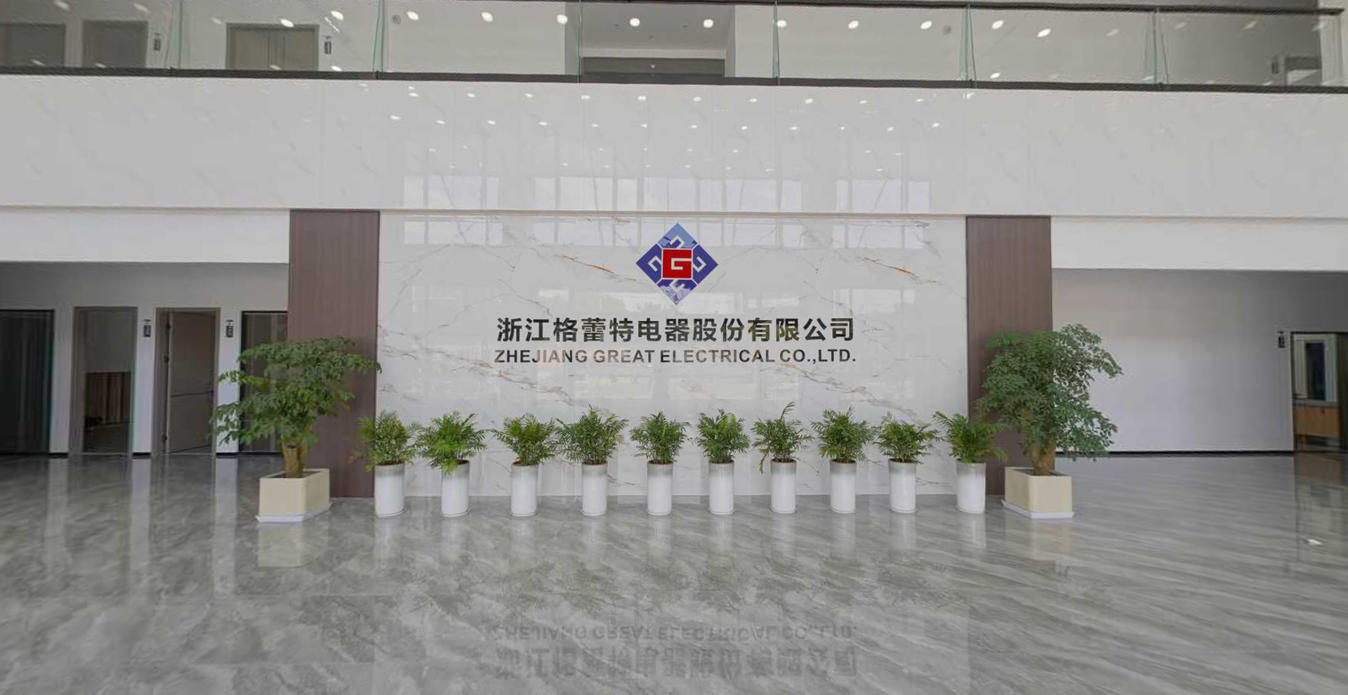
Smart home switching looks simple from the app layer: a tap should turn a load on or off. The harder question sits inside the enclosure. Does the switching element hold its state without continuous coil power? Can it carry the intended load? Does it isolate both conductors? What happens after a power cut? The GRT508BW is a 2-pole latching relay from GRT Relay, the brand of Zhejiang Great Electrical Co., Ltd., a Chinese manufacturer of latching relays, current transformers, and manganese copper shunts. For smart home switching, the GRT508BW is best understood as a bistable load-control component with an 80 A resistive switching rating, a 250 VAC maximum switching voltage, a 5–24 VDC coil range, AgSnO2 contacts, fast-connect installation, a 55.6 × 30 × 16.5 mm envelope, a -40 to +85 °C ambient range, and a 10,000-operation electrical endurance rating.
The fit is real, but it is conditional. The GRT508BW suits designs where a two-pole contact arrangement must hold position after a pulse and where steady-state coil power is undesirable. It is not a universal drop-in for every smart home load. Buyers must verify load type, inrush, pulse-drive design, thermal margin, certification scope, and the safety implications of a contact that can remain closed after supply interruption.
Why smart home switching needs a different relay question
In a conventional relay, the coil must remain energised to keep the contacts closed. That is acceptable in many industrial controls, but it is a poor match for always-on smart home equipment that is expected to sit quietly in a wall box, distribution enclosure, or appliance controller. Continuous coil current produces heat, consumes standby energy, and adds a persistent failure point. The design question changes from “which relay can switch the load?” to “which relay can switch the load, hold state, and then stop drawing coil power?”
A latching relay answers that question with a bistable magnetic structure. A pulse changes the contact position, and the relay retains that position without continuous coil excitation. That is the core value proposition for smart home switching: state memory with zero steady-state coil holding power. The trade-off is equally important. The control circuit must generate a pulse, often through an H-bridge or a dedicated pulse-driver stage, and the system must know the contact state without assuming that de-energising the coil has opened the load.
The application opportunity is therefore not “replace every relay with a latching relay.” It is narrower and more useful: identify loads that are switched occasionally, need to remain in their last state, and benefit from low standby consumption. The GRT508BW fits that evaluation because it combines a two-pole configuration with an 80 A resistive rating and a compact fast-connect package.
What the GRT508BW is, in plain terms
GRT Relay is the brand of Zhejiang Great Electrical Co., Ltd., a manufacturer established in 2003 and based in Yaozhuang Town, Jiashan County, Jiaxing City, Zhejiang Province. The company states that it develops and produces power relays, current transformers, and shunts for smart meters, smart homes, charging piles, and photovoltaic and energy storage equipment. The GRT508BW sits within that latching relay portfolio as a 2-pole model intended for load switching in smart meter, prepaid meter, smart home, and custom latching relay applications.
| Attribute | GRT508BW stated data | What it means for smart home switching |
|---|---|---|
| Contact configuration | 2-pole latching relay | Two-pole switching can be evaluated for live and neutral control, subject to enclosure and safety review. |
| Rated resistive load | 80 A | A high-current rating for resistive loads; it is not an unconditional 80 A rating for every load type. |
| Maximum switching current | 80 A | The contact current ceiling must be checked against actual load current and inrush. |
| Maximum switching voltage | 250 VAC | Defines the switching voltage boundary; higher-voltage designs need a different part. |
| Coil voltage range | 5–24 VDC | Allows low-voltage pulse drive, but the driver and pulse width must be matched to the coil. |
| Contact material | AgSnO2 | A silver-tin-oxide contact material used in the model; load testing remains necessary. |
| Installation | Fast connection | Suits assemblies designed around fast-connect terminals rather than PCB soldering. |
| Outline dimensions | 55.6 × 30 × 16.5 mm | Enclosure clearance, terminal access, and creepage must be checked against this envelope. |
| Ambient temperature | -40 to +85 °C | A wide stated range; the final enclosure temperature rise still needs validation. |
| Electrical endurance | 10,000 operations | A finite switching budget; high-cycle smart home loads need duty-cycle review. |
| Mechanical endurance | 100,000 operations | Mechanical life exceeds electrical life, so contact wear is the practical limit at rated load. |
GRT’s customer-facing material also states that the GRT508BW is RoHS compliant and compliant with IEC 62052-31 UC2. Those statements should be treated as document checks, not as automatic approval for every smart home product. The buyer should obtain the current declaration or test report and confirm that the cited standard matches the target market and product category.
How bistable operation changes the switching architecture
A latching relay is not simply a relay with a different coil. It changes the control architecture. The coil is energised for a pulse, not for the entire on-time. The contact position is held by magnetic force rather than by continuous current. In the comparison data for a conventional meter electromagnetic relay, the bistable alternative is described as pulse-current switching with state retained after power loss, zero coil current at steady state, and power consumption only within a 10–50 ms pulse. That is the mechanism that makes a low-power smart home switch feasible.
For the GRT508BW, the 5–24 VDC coil range gives the hardware team room to select a drive rail that fits the product. The important engineering work sits around that range. The pulse driver must deliver the correct polarity and duration for the chosen coil, and the firmware must avoid leaving the coil energised longer than intended. A single-coil latching relay requires polarity reversal to change state. A dual-coil version uses separate set and reset coils. The GRT508BW is a latching relay, and buyers should confirm the exact coil configuration and drive recommendation for the ordering code before layout.
The 2-pole contact arrangement is also an architectural choice. A two-pole device can be evaluated where both live and neutral conductors need switching, but the designer must not assume that a two-pole relay replaces a circuit breaker, disconnector, or isolation device. It is a load-control contact, not a complete protective function. The enclosure, terminal spacing, pollution degree, and applicable product standard remain separate design responsibilities.
The 55.6 × 30 × 16.5 mm envelope and fast-connect terminals matter in smart home products because space is tight and assembly speed matters. Fast-connect installation can reduce soldering steps in harness-based assemblies, but it also shifts attention to terminal selection, contact resistance at the interface, strain relief, and verification that the mated terminal is rated for the current. The relay’s stated ambient range of -40 to +85 °C is a component rating, not a guarantee that the surrounding enclosure stays within that range under load. Thermal testing at the enclosure level is still required.
Where the GRT508BW fits in smart home switching
The strongest fit is smart home load control where switching events are occasional and state retention is useful. Examples include smart distribution enclosures, smart switches with local load control, appliance control modules, and residential equipment that needs a remote on or off command but does not need continuous coil current. The GRT508BW’s 80 A resistive rating makes it relevant to higher-current branch loads, but that relevance must be proven against the actual load waveform. A resistive heater is a different electrical problem from a motor, a compressor, a capacitive power supply, or an LED driver with high inrush.
GRT lists smart meter, prepaid meter, smart home, and custom latching relay applications for its latching relay family. That matters for buyers because the same bistable principle is already used in metering and remote disconnect functions, where state retention and low standby power are valued. The GRT508BW can therefore be evaluated as a smart home switching part with a metering-adjacent design heritage, while the final qualification remains specific to the smart home product.
Custom assembly options broaden the fit. GRT states that custom assemblies are available with flexible wire, copper straps, or an integrated shunt. For smart home OEMs, that can reduce the gap between a bare relay and a ready-to-install subassembly. It does not remove the need for drawings, terminal validation, and sample testing. The product image set for the GRT508BW covers 2×80 A, 2×90 A, and 2×100 A pole configurations, so the ordering code and exact rating must be confirmed before a design freeze. A buyer who needs the 80 A resistive variant should not assume that every GRT508BW listing carries the same contact rating.
Adjacent GRT applications include charging piles and photovoltaic and energy storage equipment. Those are not the same as smart home switching, and they should not be treated as evidence that the GRT508BW is qualified for every residential energy system. They are useful only as portfolio context. The smart home use case must stand on its own load profile, enclosure, certification path, and failure-mode analysis.
Where it does not fit: limits buyers must verify
The first limit is load definition. The GRT508BW is rated for an 80 A resistive load and an 80 A maximum switching current at up to 250 VAC. That does not mean it can switch 80 A of motor load, compressor load, capacitive inrush, or a mixed electronic load without further validation. Smart home equipment often contains power supplies, LED drivers, and small motors whose inrush can exceed steady-state current. The buyer must test the actual load, not the nameplate current alone.
The second limit is the pulse driver. A bistable relay is not a drop-in replacement for a continuously energised relay. The comparison data notes that the bistable option requires an extra H-bridge pulse drive circuit on the PCB. That adds components, firmware states, and a new failure mode if the pulse is too short, too long, or applied with the wrong polarity. The smart home controller must also know the contact state. Because the contact can remain closed after a power cut, the system should not infer an open circuit simply because the coil is de-energised.
The third limit is maintenance and safety. The comparison data explicitly notes that load status remains after a power cut and that status check is mandatory during maintenance. In a smart home enclosure, that means a service technician could encounter a live load even after the control supply has dropped. Local isolation, status feedback, and clear service procedures are design requirements, not optional features.
The fourth limit is endurance. The GRT508BW is rated at 10,000 electrical operations and 100,000 mechanical operations. That is a finite electrical budget. A smart home load that switches several times per day will accumulate operations faster than a load that switches occasionally. The designer should compare the expected duty cycle with the 10,000-operation rating and derate where necessary. The comparison data places bistable electrical life in the 6,000 to 10,000 operation range, so the GRT508BW sits at the upper end of that range, not beyond it.
The fifth limit is compliance scope. The GRT508BW is stated to be RoHS compliant and compliant with IEC 62052-31 UC2. That is useful evidence for a document package, but it is not a blanket approval for a smart home product. The buyer must confirm the current certificate, the exact standard edition, the test conditions, and whether the target market requires additional approval. The relay’s 250 VAC maximum switching voltage also sets a hard boundary; a design that needs a higher switching voltage should not use this model.
The sixth limit is physical integration. The 55.6 × 30 × 16.5 mm envelope and fast-connect terminals must fit the enclosure, terminal block, and wiring path. Fast-connect does not remove the need to verify terminal current rating, insertion force, vibration resistance, and creepage distance. The -40 to +85 °C ambient rating is wide, but the internal temperature of a sealed smart home enclosure can be higher than the room temperature. Thermal validation at the product level is still required.
Comparison with conventional relay solutions
The conventional alternative is a continuously energised electromagnetic relay. It is simple to drive and familiar to many design teams, but it pays a standing power penalty. In the comparison data used for this guide, the bistable latching approach differs in four practical ways: it uses pulse current only for switching, it retains status after power loss, it has zero coil current at steady state, and its power consumption is limited to a 10–50 ms pulse. Static holding power is stated as 0 W.
| Decision area | Conventional continuously energised relay | GRT508BW latching approach |
|---|---|---|
| Coil power | Continuous current while the load is on | Pulse current only; zero steady-state coil current |
| State after power loss | Typically drops out when coil power is removed | Retains contact state; status check is required |
| Drive circuit | Simple transistor drive is often sufficient | Needs pulse drive, often an H-bridge, and polarity control |
| Unit cost | Lower relay unit price in the comparison data | Roughly 30% to 80% higher unit price in the comparison data |
| Life-cycle view | Standing coil losses continue over the on-time | Lower total life-cycle cost where standby power matters |
| Failure mode | Coil burnout is a known risk | Failure mainly from contact arcing; low risk of coil burnout |
This comparison does not make the latching relay universally better. The higher unit price, the extra pulse-drive circuit, and the need for state monitoring are real costs. The conventional relay remains reasonable for loads that are rarely left on, for designs that cannot accommodate a pulse driver, or for products where a normally open contact on loss of coil power is a required safety behaviour. The GRT508BW is a better fit when the smart home product values zero steady-state coil power and state retention more than drive simplicity.
Market context and long-term supply view
The wider relay market is projected to grow from USD 11.75 billion in 2026 to USD 15.65 billion by 2031, according to MarketsandMarkets. That figure covers all relay types, including electromechanical, solid-state, and latching relays. It should not be read as a latching relay forecast, a smart home switching forecast, or a statement about GRT’s market share. Its useful signal is narrower: relay demand is not static, and component selection remains a long-term supply decision rather than a one-off price comparison.
For a smart home OEM, long-term supply has three practical layers. The first is product continuity: the exact GRT508BW ordering code, coil configuration, and contact rating must remain available through the production life of the smart home product. The second is documentation continuity: RoHS declarations, IEC 62052-31 UC2 evidence, and drawing revisions should be controlled. The third is capacity. GRT reports an annual production capacity of 50,000,000 units, which is relevant to supply continuity discussions but does not replace a purchase order commitment or a capacity audit.
GRT also states that standard latching relay models are supported with 3–5 free samples for testing, with the buyer covering freight. That is useful for early evaluation, but the buyer should define the test plan before requesting samples. A sample that is tested only for basic switching will not reveal inrush behaviour, contact heating, pulse-drive margin, or state-retention safety. The sample stage should include the actual load, the actual enclosure, and the actual control firmware.
Future outlook
Smart home switching is likely to keep moving toward local intelligence: more loads controlled at the edge, more energy monitoring, and more remote disconnect functions. That direction favours switching components that can hold state without continuous coil power. It also raises the bar for verification. A low-power latching relay is only useful if the product can prove its load rating, its pulse-drive reliability, its state feedback, and its compliance path.
The GRT508BW is positioned at that intersection. Its 2-pole configuration, 80 A resistive rating, 5–24 VDC coil range, AgSnO2 contacts, fast-connect installation, compact 55.6 × 30 × 16.5 mm envelope, -40 to +85 °C range, and 10,000-operation electrical endurance make it a credible candidate for smart home load control where the load profile matches. The same facts also define the limits. Buyers should not treat the model as a universal smart switch, and they should not transfer meter-related compliance language to a smart home product without checking the exact standard and certificate.
The practical next step is an application-specific fit review: define the load, calculate the operation budget, design the pulse driver, test the enclosure thermal rise, confirm the ordering code, and validate the compliance documents. That is a more useful procurement decision than a headline current rating alone.
FAQ
What is the GRT508BW?
The GRT508BW is a 2-pole latching relay from GRT Relay, the brand of Zhejiang Great Electrical Co., Ltd. It is rated for an 80 A resistive load, a maximum switching current of 80 A, and a maximum switching voltage of 250 VAC, with a 5–24 VDC coil range, AgSnO2 contacts, fast-connect installation, a 55.6 × 30 × 16.5 mm envelope, a -40 to +85 °C ambient range, and 10,000 electrical operations.
Does the GRT508BW need continuous coil power to hold its contact state?
No. As a latching relay, it is intended to change state on a pulse and then hold position without continuous coil excitation. The comparison data for a bistable latching relay describes pulse-current switching, zero coil current at steady state, and power consumption only within a 10–50 ms pulse. The exact pulse width and coil configuration should be confirmed with GRT for the selected ordering code.
What load rating should buyers verify before using the GRT508BW in smart home switching?
Buyers should verify the actual load waveform, not only the steady-state current. The GRT508BW is rated for an 80 A resistive load and an 80 A maximum switching current at up to 250 VAC. Motor, compressor, capacitive, LED-driver, and mixed electronic loads can have inrush or phase angles that differ from a resistive load. The final rating must be confirmed by testing the real load in the real enclosure.
What drive circuit does a bistable latching relay require?
A bistable latching relay requires a pulse driver rather than a simple continuous coil supply. The comparison data notes that the bistable option needs an extra H-bridge pulse drive circuit on the PCB. The driver must apply the correct polarity and duration for the chosen coil, and the firmware must track or sense contact state. The GRT508BW has a 5–24 VDC coil range, so the drive rail and pulse energy should be matched to the selected coil variant.
What are the main limitations of the GRT508BW for smart home switching?
The main limitations are load-type dependence, pulse-drive complexity, state retention after power loss, finite electrical endurance, and compliance scope. The 80 A rating is resistive, the 250 VAC maximum switching voltage is a hard boundary, and the 10,000-operation electrical endurance is a finite budget. Because the contact can remain closed after a power cut, the product needs local isolation, status feedback, and service procedures. The stated RoHS and IEC 62052-31 UC2 compliance should be confirmed against the current certificate and the target market.
How should buyers evaluate long-term supply and customization for the GRT508BW?
Buyers should confirm the exact ordering code, coil configuration, contact rating, drawing revision, and compliance documents before design freeze. GRT states that custom assemblies are available with flexible wire, copper straps, or an integrated shunt, and that standard latching relay models are supported with 3–5 free samples for testing, with the buyer covering freight. GRT also reports an annual production capacity of 50,000,000 units. These facts support a supply discussion, but they do not replace a purchase commitment, a capacity audit, or application-specific validation.
Reference document: GRT Relay catalogue (PDF).
Have Questions or Need More Details?
Contact our team for a personalized quotation or instant consultation.
Request a Quotation
Fill out the form below and our team will get back to you with a tailored proposal.
WhatsApp Direct Chat
Prefer to chat in real-time? Message us on WhatsApp for instant assistance & quick answers.
- Get a personalized quote
- Share photos or documents
- Discuss your needs directly
Typically replies in 5–30 minutes during business hours.