
Supplier Evidence: Verifying High-Mix PCBA Capability With X-Ray and Flying Probe Data
Supplier Evidence: Verifying High-Mix PCBA Capability With X-Ray and Flying Probe Data
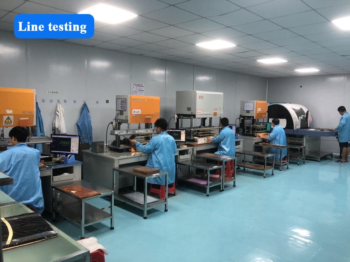
Electrical and flying probe testing produces the first verifiable record in a flexible PCB project. Image: M2PCB test line.
The global flexible printed circuit board market was estimated at USD 23.89 billion in 2024 and is projected to reach USD 50.90 billion by 2030, a compound annual growth rate of 13.7%, according to Grand View Research. The same market data shows Asia Pacific holding a 76.8% revenue share of flexible PCB industry revenue in 2024, which reflects how concentrated manufacturing capacity remains.
Growth of that scale changes what a sourcing team evaluates. When flexible circuits were mainly a handset component, mobile phone applications accounted for 55.8% of global flexible PCB market value in 2024, based on TPCA and ITRI data published via I-Connect007, and procurement could be decided on unit price and monthly output. In programmes built around artificial intelligence hardware, aerospace subsystems, new energy equipment and LED-based medical devices, the deciding question is narrower: can the supplier produce documentation that demonstrates process control on this specific design?
This reference covers the evidence layer of supplier evaluation. It explains what flying probe test data and X-ray inspection records actually verify in a high-mix printed circuit board assembly programme, uses a polyimide flexible LED PCB as the working example, and describes how a buyer can request and read those records.
Why High-Mix Programmes Expose Weak Evidence
High-mix production describes a supplier running many distinct designs, often in small quantities, through the same or adjacent lines. A single month can include a one-layer polyimide LED circuit for a therapy product and a multi-layer flex circuit for an industrial control module. M2PCB, a Shenzhen-based flexible PCB and PCBA manufacturer founded in 2000, describes its flexible PCB range as covering 1 to 14 layers and reports monthly delivery across 800 varieties.
That model only stays efficient when changeover, tooling and inspection are handled by programmable methods instead of hard tooling. This is why test strategy functions as a proxy for the wider process. A supplier able to generate a flying probe programme quickly, and to inspect assembled boards by X-ray, is a supplier whose quality control does not depend on one high-volume product.
Buyers evaluating a supplier therefore benefit from separating two questions that are often merged: what the supplier owns, in terms of equipment, floor space and headcount, and what the supplier can evidence, in terms of test records, inspection reports and certificates tied to a defined scope. Equipment lists are simple to publish. Records tied to a specific board, stack-up and date are not.
What a Flexible Printed Circuit Is, and Where Polyimide Fits
A flexible printed circuit is a printed wiring structure built on a thin polymer substrate so the finished circuit can bend or fold in service. Polyimide is the substrate most often specified when the circuit must tolerate repeated flexing or elevated soldering temperatures; FR4 is the rigid alternative, and insulated metal substrate is used where heat spreading is the primary constraint. M2PCB accepts FR4, polyimide and insulated metal substrate as base materials in its assembly service.
The polyimide flexible LED PCB is a useful illustration because it concentrates several process-sensitive features into one product. In M2PCB's specification, the flexible LED circuit board is supplied in 1 m lengths or by reel, up to 240 mm wide, with a minimum line width of 0.05 mm and minimum spacing of 3/3 mil, tested by flying probe test or electrical test, and applied in lighting, medical aesthetic and physiotherapy products. A reel-supplied LED circuit with those tolerances is a fabrication exercise in registration, adhesion and handling as much as an electrical one.
The Evidence Gap Between Stated Capability and Verified Capability
Most supplier descriptions are accurate yet difficult to verify, because they are written at the level of the factory rather than the level of the part. A statement such as the quality control sequence M2PCB publishes, covering 100% test, flying probe, electronic testing and AOI test, becomes meaningful only when it can be connected to a specific order, a specific drawing revision and a specific date.
The practical consequence for a buyer in the evaluation stage is that the supplier questionnaire should ask for artefacts rather than adjectives. Two artefact types carry the most weight early in an evaluation: bare-board electrical test output from flying probe testing, and X-ray inspection output from the assembly stage. Both are produced routinely in a normal production flow, so requesting them does not place an unusual burden on a serious supplier, and both can be compared against the drawing and stack-up the buyer supplied.
Flying Probe Test: What the Data Actually Verifies
Flying probe testing moves programmable probe heads across a fabricated board and lands them on copper features to check electrical continuity and isolation across the net list. Because probe positions come from a programme rather than a dedicated fixture, the method suits prototype and high-mix work, where the cost and lead time of building a hard fixture would be difficult to justify. M2PCB lists flying probe test as the test method for its 4-layer rigid boards, for its flexible LED PCB, and as part of its stated quality control sequence.
A flying probe report is only as useful as the information attached to it. The following elements allow a buyer to connect a test result to a purchase:
- Design identifier and revision: the part number, drawing revision and stack-up version from which the test programme was generated.
- Net count tested: how many nets the programme covers, so the buyer can confirm it matches the current artwork rather than an earlier version.
- Pass or fail result with failure detail: open circuits, shorts or isolated faults listed by net rather than summarised.
- Test method statement: confirmation that the board was tested by flying probe test or electrical test, as specified for the flexible LED PCB.
- Date and production reference: the batch and date on which the record was produced.
There is also a limit worth recognising. Flying probe access depends on probe landing geometry, so on a board with a 0.05 mm minimum line width or 3/3 mil minimum spacing, test coverage is partly a design outcome. A report showing full net coverage is evidence of both fabrication capability and design-for-test discipline, and it is reasonable for a buyer to ask how coverage is assured on tight features before the order is placed.
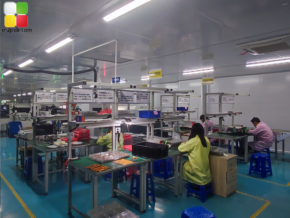
PCBA inspection follows assembly: the stage at which X-ray test records are produced. Image: M2PCB assembly and inspection line.
X-Ray Inspection: Verifying What Cannot Be Seen After Assembly
X-ray inspection is the assembly-stage counterpart to bare-board testing. In M2PCB's PCBA service, the published parameters are single-side or double-side assembly, turnkey BOM parts options, X-ray test, and program burn. X-ray examination is used to inspect solder joints that are hidden from optical view, most obviously beneath area-array packages and on double-sided assemblies, by imaging internal joint geometry and voids rather than the surface of the joint.
The distinction matters when a buyer reads a report. Optical and AOI inspection can confirm placement, polarity and visible fillet shape; X-ray adds information about internal joint formation that optical inspection cannot reach. A supplier that reports X-ray test as part of the assembly flow is offering a check on the process step that is hardest to confirm from the outside.
What X-ray data does not establish is equally important. It does not confirm the electrical function of the finished assembly, it does not test the flex endurance of the substrate in the application, and it does not verify thermal behaviour under load. Those are properties of the design and the system, and they are validated by the buyer's own prototype or qualification programme rather than by a supplier inspection report.
How M2PCB Documents Process Control
M2PCB is a group company specialising in flexible PCB fabrication and PCBA production, based at Shapuwei Industrial Zone, Songgang Street, Bao'an District, Shenzhen, China. Its published operational profile includes 600 sets of advanced production equipment and more than 30 people in technical and management roles with at least ten years of industry experience. Monthly capacity is stated at 40,000 square meters, with a quoted lead time of 3 to 20 days, a minimum order quantity of 1 unit, and customization based on the buyer's request. The company reports an export ratio of 70%, with markets in Europe, the United States, South America and Australia, and lists Europe, the United States, Brazil and the Middle East among its export markets. After-sales support is provided remotely.
Two certificates define the compliance scope that a buyer can check independently:
| Certificate | Number | Issuing body | Issued | Scope notes |
|---|---|---|---|---|
| FPC-UL | E530809 | Underwriters Laboratories Inc. (UL) | 20 March 2023 | North American market: flexible circuit boards for medical aesthetics, automotive and electronic products |
| IATF 16949:2016 | T184452 | NQA | 21 February 2024, valid to 21 February 2027 | Automotive applications: car entertainment, instrument panels, wiring harnesses, seats and related circuit boards |
These documents sit inside a wider standards framework. Safety requirements for flexible printed circuits are governed by the UL 796F standard, which addresses flammability (V-rating), maximum operating temperature and comparative tracking index specific to flexible substrates, and IPC-6013 is the internationally recognised performance specification for flexible printed wiring, detailing reliability requirements under different environmental conditions. A supplier certificate is a starting point; the standard behind it is what a buyer's engineering team will ultimately reference.
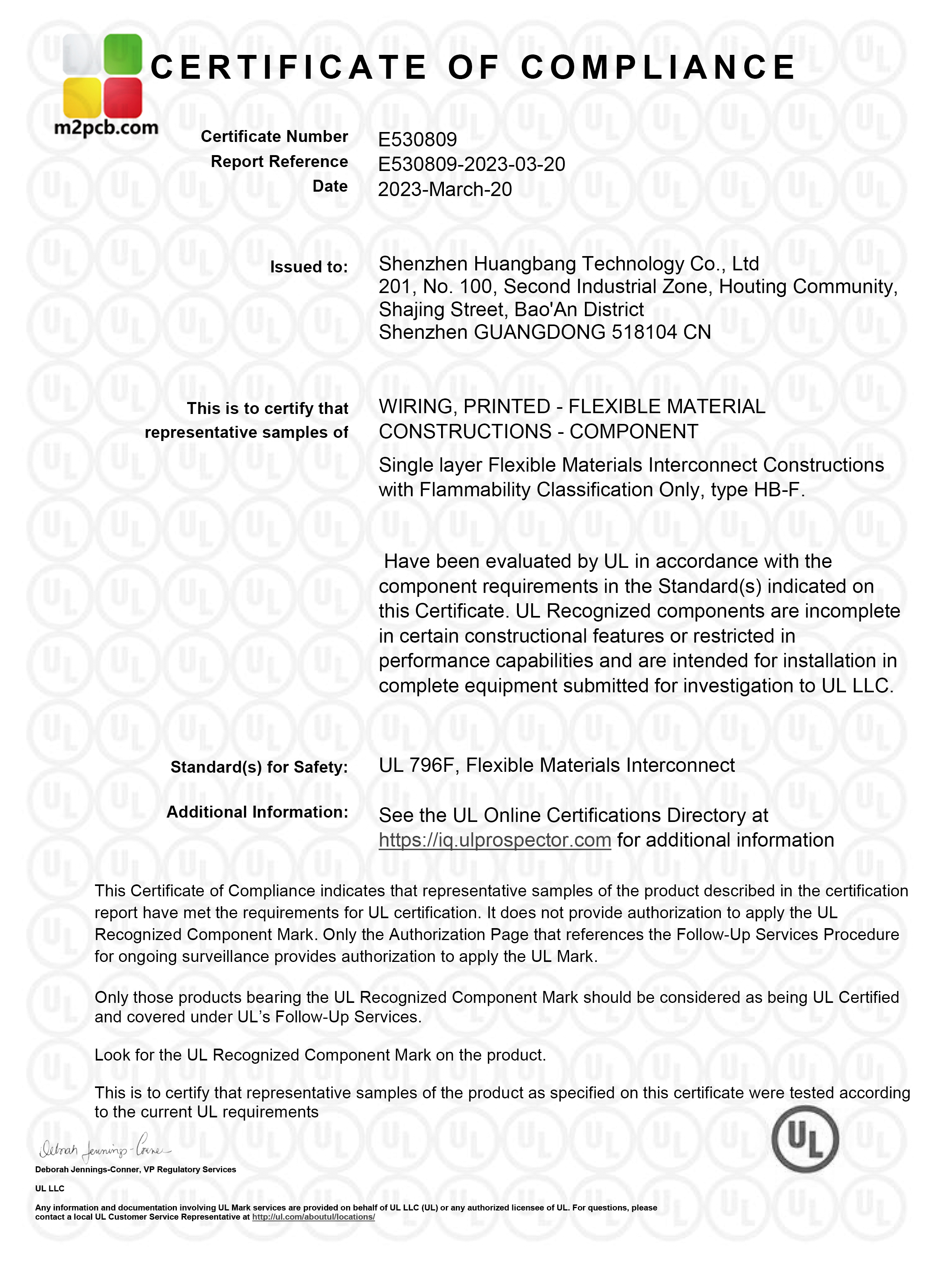
FPC-UL certificate E530809, issued 20 March 2023, covers flexible circuit boards for medical aesthetics, automotive and electronic products in the North American market.
Application: Polyimide Flexible LED PCB in Lighting and Therapy Devices
Flexible LED circuits built on polyimide are used where a light source has to follow a curved surface, be worn against the body, or be supplied on a reel for automated assembly. M2PCB's flexible LED PCB specification, covering 1 m lengths or reels, widths up to 240 mm, 0.05 mm minimum line width and 3/3 mil minimum spacing with flying probe test or electrical test, is written for the lighting, medical aesthetic and physiotherapy product industries.
A delivered example shows how these boards reach the market. A United States-based original design manufacturer of red light therapy products ordered 500,000 pieces over a two-year programme for a belt worn to relieve waist pain. The customer's product documentation describes photobiomodulation as the working principle, characterises the device as non-invasive, painless and safe, and reports that the product has been highly favoured by European and American users, with outcomes described as satisfactory. For the supplier, the relevant facts are manufacturing ones: a polyimide flexible LED circuit produced at that volume, over that duration, for a device worn against the body.
The same assembly platform serves less forgiving sectors. M2PCB lists artificial intelligence, new energy, medical electronics, and aerospace and military industries as target applications for its PCBA service, with FR4, polyimide and insulated metal substrate accepted as base materials. Those sectors are the reason the evidence discussion in this article matters: their qualification processes expect a supplier to hand over inspection records rather than assert capability.
Market Trend Analysis
Three published data points frame the direction of the category. Grand View Research estimates the global flexible PCB market at USD 23.89 billion in 2024, rising to USD 50.90 billion by 2030 at a 13.7% CAGR. Asia Pacific accounted for 76.8% of that revenue in 2024. IBISWorld projects China's printed circuit board industry revenue at USD 120.8 billion in 2024, with exports representing approximately 16.5% of total revenue.
Market concentration adds a second layer. TPCA data published via I-Connect007 places the largest global flexible PCB manufacturers in 2024 at Zhen Ding Technology with 19.9% market share, Dongshan Precision with 14.6%, and Nippon Mektron with 13.0%. Those figures describe volume leadership in high-volume segments, which remain dominated by mobile phone applications at 55.8% of global market value. They do not describe capability in every segment.
The practical reading for a buyer is that growth in flexible circuits is increasingly driven by applications that are not handsets, including automotive electronics, medical devices, energy equipment and lighting, where batch sizes are smaller and documentation demands are higher. Supplier selection in these segments is less about global volume position and more about matching a supplier's evidence trail to the buyer's qualification requirements.
Comparison With Traditional Solutions and the Boundaries of the Evidence
Polyimide flexible circuits and rigid FR4 boards solve different problems, and the inspection methods that accompany them carry different limits.
| Consideration | Polyimide flexible PCB | Rigid FR4 PCB |
|---|---|---|
| Form factor | Bends and folds; can be routed in three dimensions inside a housing | Remains flat; requires connectors or cables for out-of-plane routing |
| Typical use | Wearable and body-contacting LED products, compact medical devices, flex assemblies | Industrial control, communication equipment and consumer electronics where rigidity is acceptable |
| Assembly behaviour | Requires support and careful handling during SMT; drying and baking steps form part of the documented process | Stable through reflow with conventional carriers |
| Inspection | Flying probe test or electrical test on the bare circuit; X-ray test after assembly | Flying probe test on the bare board; impedance testing where specified |
The limits deserve as much attention as the benefits. A flying probe test verifies the electrical integrity of a fabricated flexible circuit; it does not verify the assembled product. X-ray inspection verifies internal solder joint formation; it does not verify flex-cycle endurance, adhesion after repeated bending, or thermal performance in the end application. Test coverage on fine features is partly a design outcome rather than a production one alone. Process steps such as baking before assembly add handling discipline that a buyer should see reflected in the supplier's documented workflow rather than assume.
Commercial boundaries also apply. A supplier configured for high-mix, low-volume flexibility, with a minimum order quantity of 1 unit and a 3 to 20 day lead time, is not automatically the lowest-cost option at very large single-design volumes, where dedicated tooling amortises differently. M2PCB's stated after-sales model is remote support, which suits buyers with in-house engineering capability but may be insufficient for teams that require on-site field service. These are trade-offs to weigh against the evidence trail, not defects.
Requesting and Reading Test Reports: A Procurement Checklist
| Evidence document | What it verifies | What it does not verify |
|---|---|---|
| Flying probe test report (bare flexible or rigid board) | Net continuity and isolation against a programme generated from the current artwork revision | Assembled function; flex life in the application |
| X-ray inspection record (assembled board) | Internal solder joint geometry on single-side or double-side assemblies | Electrical function, thermal performance or mechanical endurance |
| AOI and 100% test records | That the stated quality control sequence was applied to the batch | Design-level qualification of the end product |
| UL and RoHS material documentation | That materials used carry recognised approvals | Certification of the finished product |
| FPC-UL certificate E530809 | UL recognition for flexible circuit boards within the stated scope for the North American market | Product types outside the stated certificate scope |
| IATF 16949:2016 certificate T184452 | Automotive quality management certification, valid to 21 February 2027 | Applications outside the listed automotive scope |
| Turnkey BOM and program burn records (PCBA) | Parts sourcing traceability and completion of programming steps | Firmware or system performance in the end application |
Future Outlook
Two directions look reasonably clear from the available evidence. First, documentation is becoming part of the product. Standards such as IPC-6013 for flexible printed wiring and UL 796F for flexible substrate safety set the vocabulary buyers use in supplier qualification, and suppliers able to attach those references to a specific order will be easier to approve.
Second, the application mix is broadening beyond handsets, which pushes value toward suppliers that handle variety well. Flexible PCB volume leadership, as measured by 2024 market share, sits with a small number of large manufacturers, while a substantial share of new demand arises in medical, automotive and energy applications where batch sizes differ. For evaluation-stage buyers, the practical consequence is unchanged: the supplier that can produce a flying probe report and an X-ray record for the exact board under discussion is the supplier whose stated capability can be relied upon.
Frequently Asked Questions
What documents should a buyer request when verifying a PCBA supplier's inspection capability?
Request the bare-board electrical test method, whether flying probe test or electrical test, the assembly parameters including whether the supplier supports single-side or double-side assembly and turnkey BOM parts options, and confirmation of X-ray test and program burn in the assembly flow. M2PCB publishes all of these as stated service parameters, together with a quality control sequence of 100% test, flying probe, electronic testing and AOI test.
How does a flying probe test differ from X-ray inspection in a flexible PCB and PCBA workflow?
They operate at different stages. Flying probe testing is applied to the fabricated board before assembly and checks electrical continuity and isolation across the net list using programme-driven probes rather than a dedicated fixture. X-ray inspection is applied after assembly and images internal solder joints that optical inspection cannot see. M2PCB specifies flying probe test or electrical test for its flexible LED PCB and lists X-ray test as a PCBA parameter.
Why is polyimide used for flexible LED PCBs?
Polyimide is the substrate specified for M2PCB's flexible LED circuit board, which is supplied in 1 m lengths or by reel, up to 240 mm wide, with a minimum line width of 0.05 mm and minimum spacing of 3/3 mil, and tested by flying probe test or electrical test. The published application scope for this product is the lighting, medical aesthetic and physiotherapy industries, where the circuit has to follow a curved or body-contacting surface.
Which certificates support a flexible PCB supplier's claims for medical, automotive and North American markets?
Two certificates define M2PCB's stated scope. FPC-UL certificate E530809, issued by Underwriters Laboratories Inc. on 20 March 2023, covers flexible circuit boards for medical aesthetics, automotive and electronic products in the North American market. IATF 16949:2016 certificate T184452, issued by NQA on 21 February 2024 and valid to 21 February 2027, covers automotive applications such as car entertainment, instrument panels, wiring harnesses and seats. The relevant underlying standards are UL 796F for flexible substrate safety and IPC-6013 for flexible printed wiring performance.
How does a high-mix production model affect lead time and sampling?
M2PCB states a minimum order quantity of 1 unit, a lead time of 3 to 20 days, and customization based on the buyer's request, supported by a monthly capacity of 40,000 square meters and monthly delivery across 800 varieties. That combination suits validation-first purchasing, in which a buyer evaluates samples and prototypes before committing to volume.
What are the limits of inspection data when evaluating a supplier?
Flying probe testing verifies the electrical integrity of the fabricated circuit against a programme derived from a specific artwork revision, and its coverage depends on probe access on fine features. X-ray inspection verifies internal solder joint formation but not assembled function, flex endurance or thermal behaviour. Certificates apply to the scope stated on the certificate rather than to every product a supplier offers, and M2PCB's after-sales support is provided remotely rather than on site. Supplier inspection data should be treated as one input alongside a buyer's own prototype and qualification testing.
For evaluation-stage buyers working through a shortlist, the decisive difference between suppliers is usually not the equipment list but whether a test record can be produced that matches the drawing, the stack-up and the assembly side being quoted. M2PCB's published capability data and certification scope are available through www.m2pcb.com.