
U.S. vs. Canada Pad Mounted Transformers: Certification and Fault Duty
U.S. vs. Canada Pad Mounted Transformers: Certification and Fault Duty
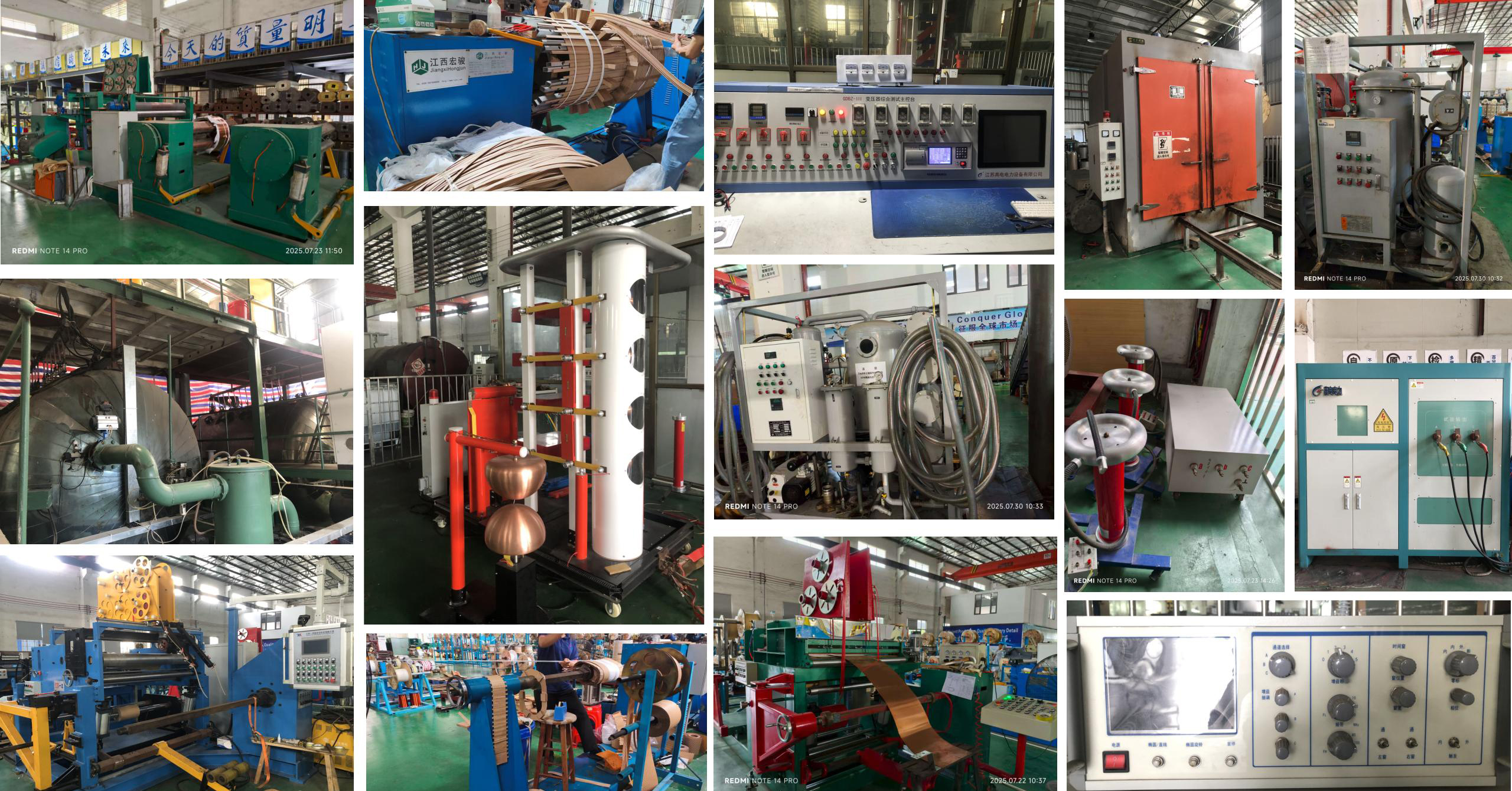
Transformer production and testing equipment. Certification scope and test evidence, not catalogue capacity, usually decide a North American pad mounted transformer award.
North American utilities, EPC contractors and industrial buyers rarely select a pad mounted transformer on capacity alone. By the time a project reaches the evaluation stage, the deciding questions are narrower: whether the unit's certification actually covers the voltage class and kVA being purchased, and whether its short-circuit withstand capability matches the fault envelope at the point of interconnection. Those two questions are answered in different ways in the United States and Canada, and the difference is a procurement problem before it becomes an engineering one.
This comparison sets out how U.S. and Canadian policy and certification requirements diverge for liquid-filled pad-mounted distribution transformers, how evaluation teams should test short-circuit withstand claims inside each regime, and what a factory needs in order to build to a custom withstand requirement under an ODM arrangement. It is written for buyers comparing sourcing routes, not for buyers comparing brochures.
Why Fault Duty Decides the Specification Before kVA Does
A pad-mounted transformer is installed close to the feeder it serves, which places it near the highest fault contribution on the distribution system. During a through-fault, the winding assembly carries mechanical forces proportional to the square of the fault current, and it must remain serviceable until upstream protection clears the circuit. Short-circuit withstand is therefore not a generic product attribute. It is a project parameter derived from three inputs the buyer owns: available fault current at the point of interconnection, protection clearing time, and system grounding.
Impedance is the lever that moves fault current, but it is not a free lever. Raising percent impedance reduces fault duty while widening voltage regulation and shifting protection coordination. Lowering it improves regulation and increases the mechanical duty the winding must survive. Because that trade-off is settled at the design stage, short-circuit parameters belong in the first technical exchange with a factory rather than in a post-award clarification.
The design basis is shared across the border. For three-phase pad-mounted, compartmental-type, self-cooled distribution transformers of 10 MVA and smaller, IEEE C57.12.34 is the governing standard, and IEEE C57.12.34-2022 is the current active edition. Canadian qualification adds CSA C227 as the standard cited in cUL certification scopes for pad-mounted units. The standards converge; the certification paperwork does not.
Two Compliance Paths, One Shared Design Language
The table below summarises how the two markets are addressed in an actual certificate set held by a pad mounted transformer manufacturer, using Xiamen Winley Electric Co., Ltd as the reference case. Every scope figure shown is taken from the company's UL Solutions certificates.
| Dimension | United States | Canada |
|---|---|---|
| Certification mark | UL listing issued by UL Solutions | cUL certification issued by UL Solutions |
| Standard cited in certificate scope | ANSI/IEEE C57 | CSA C227 |
| Design standard for three-phase pad mount (10 MVA and smaller) | IEEE C57.12.34-2022 | CSA C227, applied alongside IEEE practice |
| Certificate number, pad-mounted transformers | E536138 | E536138 |
| Three-phase scope | 45 to 5000 kVA; HV up to 36.0 kV | 45 to 5000 kVA; HV 26.0 kV to 36.0 kV |
| Single-phase scope | 10 to 250 kVA; liquid-filled, pad-mounted | 10 to 250 kVA; liquid-filled, pad-mounted |
| Efficiency reference named in the evidence set | DOE 2016 minimum efficiency | Confirm against the destination market specification |
Scope figures reflect Winley Electric certificates E536138 (UL and cUL) and the IEEE C57.12.34-2022 standard reference. Buyers should verify the current certificate revision at the time of award.
One detail in this table carries more commercial weight than its size suggests: the U.S. and Canadian marks for pad-mounted units sit under the same certificate number, E536138. Dual coverage under a single certificate streamlines documentation for projects that straddle the border, but it does not make the two scopes identical. The Canadian three-phase scope begins at 26.0 kV high voltage, while the U.S. scope extends down from 36.0 kV without a stated lower bound in the same phrasing. That asymmetry is exactly the kind of detail an evaluation-stage buyer must read before relying on the mark.
Reading the Scope Line: Where Coverage Actually Ends

Certificate E536138 covers three-phase pad-mounted transformers from 45 to 5000 kVA. The Canadian scope states a 26.0 kV to 36.0 kV high-voltage window.
A listing is a statement about a defined envelope, not a statement about a product family in general. Three boundaries matter in practice.
Boundary one: voltage class below the Canadian window
Many Canadian distribution projects operate at medium-voltage classes below the 26.0 kV lower bound shown on the cUL scope. A buyer evaluating such a project cannot assume the mark transfers because the same manufacturer also holds a U.S. listing up to 36.0 kV. The correct action is a written scope confirmation against the exact voltage ratio in the specification, requested before the purchase order rather than during the inspection.
Boundary two: single-phase capacity ceiling
Both listings stop at 250 kVA for single-phase liquid-filled pad-mounted units, starting at 10 kVA. A specification calling for a larger single-phase pad mount therefore sits outside the listed envelope on both sides of the border, regardless of how capable the factory is at building it. Capability and certification are separate questions, and only one of them can be answered by a datasheet.
Boundary three: efficiency basis
DOE 2016 minimum efficiency appears explicitly in the manufacturer's evidence set, which is a U.S. requirement. Canadian efficiency compliance should be confirmed against the destination specification item by item rather than inherited from the U.S. statement. Reviewers who treat the two as interchangeable create a compliance gap that surfaces late, at a point where it is expensive to close.
How Buyers Evaluate Short-Circuit Withstand Capability
Short-circuit withstand is evaluated through a documented sequence rather than a single number. The sequence below reflects how an evaluation-stage buyer can interrogate the requirement without depending on a supplier's marketing narrative.
- Fix the fault envelope first. Available fault current at the point of interconnection, protection clearing time and system grounding together define the withstand current and duration the transformer must tolerate. Without these three inputs, no withstand figure is meaningful.
- Set an impedance window, not a single value. Specify percent impedance with a tolerance band, and confirm the resulting voltage regulation and protection coordination remain acceptable at the extremes of that band.
- Review the mechanical design behind the claim. Winding conductor material and section, radial and axial bracing, core clamping and tank stiffness determine whether the assembly survives a through-fault. A withstand figure without a design description is an assertion.
- Define the evidence package. Ask which design calculations, routine test records and type test reports will be delivered, and whether the buyer will witness testing. Factory routine tests and type tests are performed as per customer requirements at Winley Electric, which means the requirement has to be written into the specification to exist.
- Confirm the certification scope covers the design. A transformer that meets the fault requirement but sits outside the certificate envelope is a documentation problem at energisation.
- Lock accessories and protection interfaces. Gauges, switches, protection devices, monitoring and communication interfaces are part of the fault-clearing path and belong in the same technical annex as the withstand requirement.
A shortlist scorecard for the evaluation stage
The scorecard below converts the sequence into comparable criteria. It is designed to be used identically against a domestic stock supplier and an ODM manufacturer, so that preference decisions rest on evidence rather than on familiarity.
| Criterion | Evidence to request | What a pass looks like |
|---|---|---|
| Certification scope fit | Certificate number, kVA range, voltage range, standard cited | Project voltage and kVA fall inside the stated envelope for the destination country |
| Fault-duty engineering | Impedance window, bracing description, withstand current and duration | Withstand basis traces to the buyer's fault level and clearing time, not to a default |
| Test evidence | Routine test list, optional type tests, witness arrangements | Tests are itemised in the specification and accepted before production |
| Customisation depth | Electrical, structural and accessory change options | Changes are engineering work, not accessory swaps |
| Delivery credibility | Lead time, monthly capacity, minimum order quantity | Committed schedule is consistent with the project's energisation date |
| Post-delivery support | Warranty start point, duration, spare and technical support terms | Coverage terms are explicit and start at a defined milestone |
Submitting an ODM Short-Circuit Requirement: The Data Pack
Under an ODM arrangement, the buyer is not selecting from a catalogue; the buyer is transferring a design intent. The quality of that transfer determines the quality of the quotation. Winley Electric's ODM scope covers electrical performance including rated capacity, voltage and connection group, structural and appearance items, insulation fluid, protection devices, switches, gauges, tank coating, extreme-environment adaptation, and monitoring, protection and communication interfaces, with engineering capability up to 10 MVA and high-voltage systems rated up to 36 kV. Component integration from suppliers such as Qualitrol and Eaton Cooper is also offered for tailored designs.
| Data field | What the buyer should state | Why the factory needs it |
|---|---|---|
| Rated capacity | kVA, with the design duty behind it | Sets winding geometry and the mechanical frame that resists fault forces |
| Voltage ratio and connection group | HV and LV voltages, vector group, winding arrangement | Defines insulation levels and the fault current path |
| Tap range | Number of taps and percentage steps | Affects impedance at each tap position and therefore fault duty |
| Impedance | Percent impedance with tolerance band | Controls fault current, regulation and protection coordination |
| Fault duty | Withstand current and duration derived from the project fault level | Drives bracing, conductor section and clamping design |
| Protection context | Upstream device type and clearing time | Confirms the withstand duration is realistic for the scheme |
| Grounding | System grounding arrangement | Changes fault current magnitude and insulation stress |
| Certification scope | UL only, or UL and cUL | Determines which certificate envelope the design must stay inside |
| Efficiency basis | DOE 2016 or project-specific minimum | Fixes core and conductor design trade-offs |
| Enclosure and feed | Radial or loop feed, dead-front arrangement, cabinet size, protection class | Structural and safety configuration, not cosmetic choice |
| Insulation fluid | Fluid type and any environmental constraint | Affects thermal performance and site approvals |
| Accessories | Gauges, switches, protection devices, communication interfaces | Defines the monitoring and protection envelope |
| Test and witness plan | Routine tests required, type tests required, witness points | Type tests are performed as per customer requirements and must be requested |
| Documentation | Drawing approval stages, nameplate data, final record package | Prevents scope drift between approval and shipment |
Two practical notes on this data pack. First, the fault duty row is the one buyers most often leave blank, because the project's protection study is not yet final. Submitting a placeholder and adjusting later is acceptable only if the impedance window is reopened; a fixed impedance combined with a changed fault level produces a design that satisfies neither document. Second, the certification row is not a formality. If the destination is Canada and the high voltage falls below the cUL scope's 26.0 kV lower bound, that needs to be resolved as a technical question, not discovered as a labelling question.
Inside the Factory Side of the ODM Route
Xiamen Winley Electric Co., Ltd is a transformer manufacturer founded in 2014 and headquartered in Xiamen, China, with manufacturing facilities in Shanghai and Guangdong. The company produces three-phase pad-mounted transformers, single-phase pad-mounted transformers, substation transformers, pole-mounted transformers, cast coil and vacuum-impregnated transformers, isolation and control transformers, voltage regulators and reactors, and states manufacturing capability for high-voltage power transformers up to 450 MVA and 230 kV.
Several operational facts are directly relevant to an evaluation-stage short-circuit discussion rather than to a general company profile. The company reports a 45,000 m² factory footprint, 220 employees, an annual output of 35,000 units, a 35-engineer R&D team and a 70% export ratio concentrated on North and South America, with products exported to more than 60 countries. For ODM work it states a monthly capacity of 500 units, a lead time of 4 to 8 weeks and a minimum order quantity of one unit. Quality management is certified to ISO 9001, ISO 14001 and ISO 45001, and the factory operates type test equipment including lightning impulse test devices alongside conventional routine test equipment.
Certification evidence is where the U.S. and Canadian comparison becomes concrete. The three-phase pad-mounted line is UL and cUL listed under certificate E536138 for 45 to 5000 kVA, with high voltage up to 36.0 kV on the U.S. scope and 26.0 kV to 36.0 kV on the Canadian scope, citing ANSI/IEEE C57 and CSA C227 respectively. The single-phase pad-mounted line carries the same certificate number for 10 to 250 kVA. The company's dry-type general transformer line is separately listed under E531446. Standard three-phase ratings are stated as 75 to 5000 kVA.
A delivery record supports the scope claims. A U.S. electricity utility client took delivery of 31 units of three-phase pad-mounted transformers covering 2550 kVA and 3750 kVA, at high voltages of 34.5 kV and 12.87 kV, produced to the client's application conditions and North American standards, with the full series UL and cUL listed and core efficiency metrics meeting or exceeding DOE 2016 requirements.
Rating Classes and Application Fit
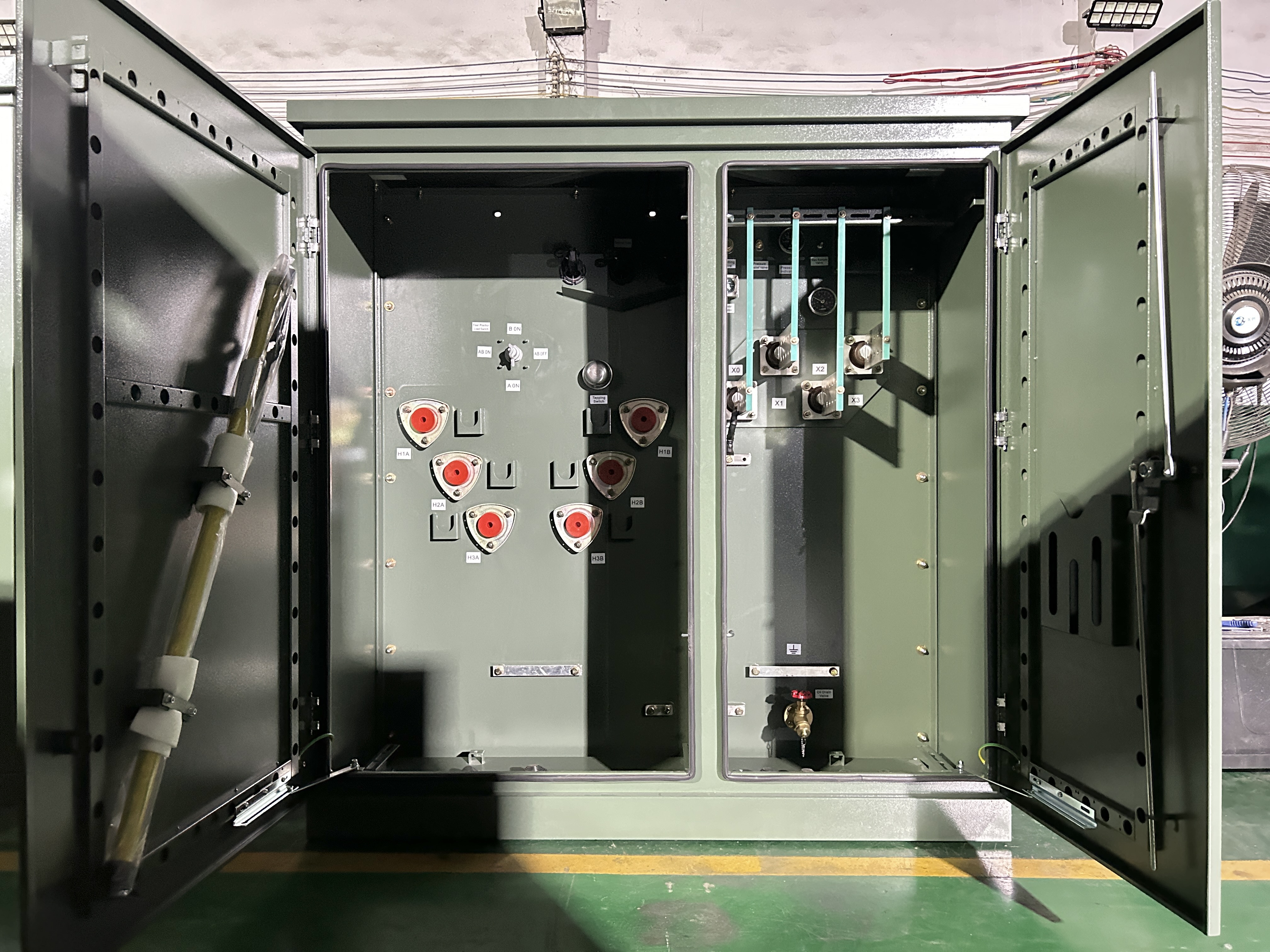
A 300 kVA three-phase oil-immersed pad-mounted distribution transformer rated 12870 V to 208 V. Medium-voltage classes in this range require an explicit scope check against the Canadian certificate window.
Rating class selection is where the certification envelope meets the application. The table below maps common requirement bands to listed coverage and to the scope question a buyer should raise.
| Requirement band | Listed coverage in the reference certificate set | Scope question for the buyer |
|---|---|---|
| Single-phase residential and small commercial, 10 to 250 kVA | UL and cUL, 10 to 250 kVA | Confirm the LV configuration; capacity above 250 kVA falls outside the listing |
| Three-phase commercial and light industrial, 45 to 500 kVA | UL and cUL, 45 to 5000 kVA | For Canada, confirm the HV class sits within 26.0 kV to 36.0 kV |
| Three-phase utility distribution, 750 to 2500 kVA | UL and cUL, 45 to 5000 kVA | Fault duty and impedance window become the binding constraints |
| Three-phase large commercial, data centre and renewables, 2550 to 3750 kVA | UL and cUL, up to 5000 kVA; delivered units at 2550 kVA and 3750 kVA | Confirm enclosure, cooling and accessory package in the same annex |
| Above 5000 kVA, or ODM engineering beyond 36 kV | Outside the pad-mounted listing envelope; ODM capability stated to 10 MVA and 36 kV | Treat certification as a project-specific question, not an inherited one |
Solar, utility distribution and electric vehicle charging projects share a common pattern: the transformer sits close to inverters or chargers that shape the fault contribution and the harmonic environment, so the short-circuit requirement cannot be copied from an earlier project of similar kVA. The rating class is the starting point for the conversation, not the answer to it.
Market Signals Buyers Should Weigh
Demand-side pressure is a legitimate part of an evaluation, provided the numbers are attributable. Commercial research cited in HTNXT's verified data package estimates the U.S. pad-mounted transformer market at USD 3,750.0 million in 2024, with a forecast of USD 8,320.0 million by 2035 across a 2025 to 2035 forecast period. The same research characterises the global field as concentrated, attributing approximately 21% share to ABB and 18% to Schneider Electric in 2025; that figure is commercial research of medium confidence and should be read as directional rather than precise.
Two implications follow for buyers. A growing replacement and grid-modernisation market keeps pressure on delivery schedules, which raises the value of manufacturers that can commit to a lead time against a documented capacity figure. At the same time, concentration among established brands means the alternatives most worth evaluating are the ones with verifiable certification scope rather than the ones with the loudest capacity claims. Neither implication removes the need to match the certificate to the project.
Certified ODM Build vs. Domestic Stock: An Honest Comparison
The comparison that matters at the evaluation stage is not brand against brand. It is sourcing route against sourcing route, measured on the same criteria.
| Dimension | Domestic stock unit | Certified ODM build |
|---|---|---|
| Certification scope | Listed for the domestic market; cross-border use requires separate confirmation | UL and cUL coverage available under one certificate number, bounded by kVA and voltage scope |
| Short-circuit fit | Constrained to the impedance and withstand values already built | Impedance window, bracing and withstand duration specified to the project fault envelope |
| Customisation depth | Accessory-level changes | Electrical performance, structure, insulation fluid, protection and communication interfaces |
| Lead time | Immediate if the rating is in stock | 4 to 8 weeks stated for ODM work |
| Order size | Subject to stock allocation | Minimum order quantity of one unit |
| Test evidence | Standard routine test records | Routine and type tests as per customer requirements, with impulse test equipment on site |
| Documentation burden on the buyer | Low | Higher: the specification must be complete before quotation |
The honest boundary of the ODM route is documentation, not capability. An ODM build places the specification burden on the buyer: fault level, clearing time, impedance window, type test list and certification scope all have to be stated, because factory type tests are performed as per customer requirements rather than issued by default. Buyers who arrive without those inputs will receive a quotation built on assumptions, and the assumptions will be theirs by default.
A second boundary concerns warranty structure. After-sales coverage runs for 24 months from the bill of lading, with free replacement of damaged accessories against photographic evidence and technical support available on request. The clock therefore starts at shipment, not at commissioning. On a project with a long storage or installation window, part of that coverage is consumed before the transformer is energised, and buyers should price that reality into their schedule rather than discover it at the first claim.
What Changes Next
Three developments are worth tracking for buyers who evaluate pad-mounted transformers across the U.S. and Canadian markets. IEEE C57.12.34-2022 is the current edition of the three-phase pad-mounted standard, and specifications still referencing earlier editions should be reviewed for alignment. Dual UL and cUL coverage under a single certificate streamlines cross-border documentation, but it does not harmonise the underlying scope statements, so scope discipline will remain a buyer responsibility. And as replacement and grid-modernisation demand continues, the manufacturers that stay on shortlists will be those able to evidence scope, fault-duty engineering and test records as a package rather than as separate claims.
Click to view more pad‑mounted transformer projects from Winley Electric:https://www.winley-electric.com/supplier-4701740-three-phase-pad-mounted-transformer
·Website:www.winley-electric.com
FAQ
Does a UL listing automatically make a pad-mounted transformer acceptable in Canada?
No. U.S. acceptance rests on a UL listing against an ANSI/IEEE C57 basis, while Canadian acceptance is expressed through cUL certification citing CSA C227. Where both marks are held under the same certificate number, as with E536138 for pad-mounted units, dual coverage exists but remains bounded by the kVA and voltage ranges stated for each country. A Canadian three-phase scope of 45 to 5000 kVA at 26.0 kV to 36.0 kV is not the same statement as a U.S. scope extending to 36.0 kV, so the project's voltage class should be matched to the certificate line by line.
What short-circuit information should an RFQ contain?
At minimum: available fault current at the point of interconnection, upstream protection type and clearing time, the required withstand current and duration, percent impedance with a tolerance band, system grounding, rated capacity and voltage ratio, connection group, tap range, the certification scope required for the destination country, the efficiency basis, and the list of routine and type tests to be performed and witnessed. Without the fault level and clearing time, a withstand requirement has no engineering meaning.
Which ratings are covered by the pad-mounted certificates referenced in this comparison?
Under certificate E536138, three-phase liquid-filled pad-mounted transformers are covered from 45 to 5000 kVA with high voltage up to 36.0 kV for the United States and 26.0 kV to 36.0 kV for Canada, and single-phase liquid-filled pad-mounted transformers are covered from 10 to 250 kVA in both markets. Winley Electric states a standard three-phase range of 75 to 5000 kVA and ODM engineering capability up to 10 MVA and 36 kV, which is a manufacturing statement rather than a listing statement.
How long does a custom ODM pad-mounted transformer take, and what is the minimum order?
Winley Electric states a lead time of 4 to 8 weeks for ODM work, a monthly capacity of 500 units and a minimum order quantity of one unit. Schedule commitments should be read together with the specification completeness, because the lead time assumes an approved design and an agreed test plan.
Are type tests included as standard on a custom build?
Factory routine tests are performed as standard, and type tests are performed as per customer requirements. That means the type test list has to be written into the specification and agreed before production. The factory operates type test equipment including lightning impulse test devices alongside conventional testing equipment, so the buyer's task is to state which tests are required and whether witnessing is expected.

Have Questions or Need More Details?
Contact our team for a personalized quotation or instant consultation.
Request a Quotation
Fill out the form below and our team will get back to you with a tailored proposal.
WhatsApp Direct Chat
Prefer to chat in real-time? Message us on WhatsApp for instant assistance & quick answers.
- Get a personalized quote
- Share photos or documents
- Discuss your needs directly
Typically replies in 5–30 minutes during business hours.