
USB Connector Scenario Fit: Portable SSD & USB4.0 Docking
Scenario Fit · USB Type-C Interconnect
USB Connector Scenario Fit: Portable SSD & USB4.0 Docking
A USB Type-C receptacle is the only component in a portable SSD or a docking station that is at once a structural element, a mating interface and a segment of the high-speed channel. Two products that both read “USB4.0 Type-C” on a datasheet can therefore have almost nothing in common at the connector level — because the enclosure, the PCB stack-up and the signal budget place opposite demands on the same interface.
For design and procurement teams in the Research-to-Evaluation stage, the useful question is not which USB-C socket is “best”, but which mechanical format fits a specific enclosure and which evidence actually supports the data-rate claim printed on the box. This article works through that question for two high-volume product families: the pocketable portable SSD and the multi-port USB4 docking station.
The commercial backdrop is well documented. The global USB Type-C market was estimated at USD 38.96 billion in 2024 and projected at USD 48.33 billion in 2025, according to a Market Research Future report published in September 2026. On the regulatory side, Directive (EU) 2022/2380 made USB Type-C the common charging port for defined device categories from 28 December 2024, with the requirement extended to laptops from 28 April 2026. Both product families sit inside that demand band, and both inherit the same connector-level questions.
Two scenarios, two opposite connector briefs
Portable SSDs and docking stations are frequently discussed together because both are “USB-C devices”. Mechanically and electrically, they pull in different directions.
The portable SSD brief: subtract millimetres
- Enclosure thickness is the dominant constraint. A pocketable SSD competes on volume, and the socket is usually the tallest single component on the board. Every 0.5 mm saved at the connector translates into a thinner shell or a larger battery.
- The PCB is small, thin and often low-layer. There is little room for a connector cavity, and even less for reinforcement.
- The socket is a load-bearing surface. Users plug and unplug by holding the drive body, so insertion force is transmitted into the housing rather than into a chassis.
- Thermal headroom is contested. The controller heats up during sustained writes, and the connector sits in the same thermal zone. Operating temperature range matters as much as data rate.
- Port count is typically one or two. The connector is not sharing board area with DisplayPort, RJ45 or USB-A.
The USB4 docking brief: add ports, add power, protect the channel
- Board area is abundant, height is not unlimited. A dock usually has a larger PCB but must still present its ports flush with a moulded front panel.
- The power path is heavier. USB Power Delivery Extended Power Range supports up to 240 W, and high-power USB Type-C connectors and cables are specified in a 5 A current class. That is a different contact and thermal problem from a signal-only port.
- Several protocols share one connector. USB4 is defined as an architecture that extends USB Type-C performance and supports multiple simultaneous data and display protocols, so the socket sits at the junction of data, video and power.
- Downstream ports multiply the risk. A dock may carry USB-C, USB-A, HDMI or DisplayPort, and sometimes an internal NGFF M.2 slot for storage expansion — each with its own mechanical and signal requirements.
Mounting geometry: top-mount, mid-mount and flag-type
The three formats that dominate USB Type-C board design are not cosmetic variants. They change where the connector sits relative to the PCB, and therefore what the enclosure engineer can do.
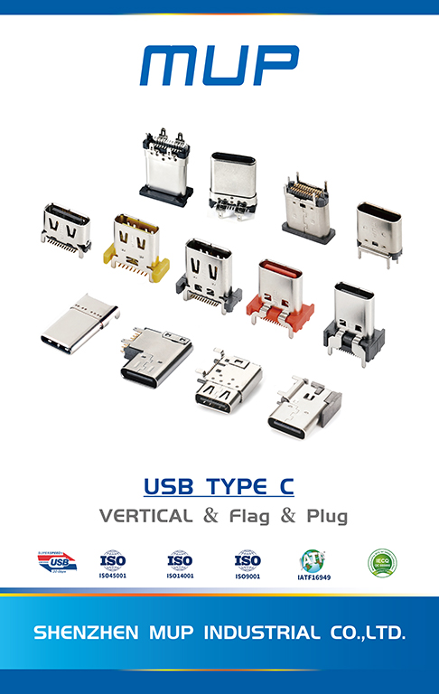
A top-mount USB receptacle sits entirely above the board surface. It is the simplest to place, the easiest to inspect after reflow, and the most tolerant of PCB rework, but it contributes its full height to the internal stack. A mid-mount USB-C socket is recessed into a cut-out in the PCB so that part of the housing sits within the board thickness. This reduces the height above the board, which is precisely what a slim enclosure needs, but it requires a routed cavity, adds machining tolerance to the assembly, and removes material from the board exactly where the connector is levered during mating. A flag-type USB-C connector orients the mating axis parallel to the board, so the cable enters from the side rather than from above. That suits enclosures with a side opening and limited board-to-cover clearance, and it changes how insertion force is transferred into the housing.
| Attribute | Top-mount receptacle | Mid-mount socket | Flag-type |
|---|---|---|---|
| Position relative to PCB | Fully above the board surface | Partly recessed into a board cut-out | Body beside the board edge, mating axis parallel to the board |
| Height contribution to the enclosure | Highest | Reduced by the recessed depth | Low profile in the vertical direction, wider in the horizontal |
| PCB requirement | Standard SMT pad layout | Routed cavity plus SMT pads; tighter mechanical tolerance | Edge placement with clearance for housing and cable |
| Typical enclosure opening | Top or rear face | Top or rear face, flush with a thin cover | Side face |
| Mechanical retention | Governed by solder joints and housing | Governed by joints plus cavity walls | Governed by joints plus surrounding structure |
| Best fit | Docks, hubs, industrial panels with vertical room | Slim portable SSDs, ultra-thin docks | Devices with side-entry ports and shallow internal height |
| Watch-outs | May exceed the internal height budget | Board strength and machining tolerance | Cable bend radius and panel cut-out accuracy |
Read as a design rule, this table produces a short decision path. If the internal height budget is generous and serviceability matters, top-mount is usually the lower-risk choice. If the enclosure is defined by a thickness target, mid-mount is the format that buys the millimetres. If the industrial design puts the port on a side face, flag-type is the format that removes the conflict between cable direction and internal height.
Shenzhen MUP Industrial Co., Limited (MUP), a National High-Tech Enterprise founded in 2003 that designs and manufactures precision connectors and cable assemblies from bases in Shenzhen, Huizhou and Dongguan, lists top-mount USB connectors, mid-mount USB sockets, flag-type USB-C and waterproof variants within its USB Type-C range. The range is catalogued across models including the U20401, U20402, U20404, U20405, U20411, U22401, U22402, U22403, U22408, U20418 and U20419 series, with electrical parameters stated as 50 V maximum rated voltage, an operating range of −40 °C to 85 °C and a durability rating of 10,000 to 15,000 mating cycles.
Decision rule for the two scenarios. A pocketable SSD is height-constrained and port-poor, so mid-mount or flag-type geometry usually earns its extra process step. A docking station is height-tolerant and port-rich, so top-mount geometry usually wins on assembly simplicity and inspection — unless the industrial design forces a side-facing port.
What a USB4.0 or Thunderbolt 5 claim actually covers
This is where procurement reviews most often go wrong. The headline data rates are specification-level statements, not connector-level measurements.
USB4 Version 2.0 specifies data rates up to 80 Gbps. Thunderbolt 5, as stated by Intel, supports 80 Gbps bidirectional with a Bandwidth Boost mode reaching 120 Gbps. These figures describe interface capability under defined conditions; they do not certify that a particular receptacle, at a particular board location, will deliver that throughput in a particular enclosure. Connector-level performance depends on impedance control, insertion loss, crosstalk and the mechanical quality of the mating interface, none of which is implied by the system-level number.
For a buyer, the practical translation is that “supports USB4.0” should be separated into three distinct claims, each verified differently:
- Specification support — the connector family is designed against the USB Type-C Cable and Connector Specification published by the USB Implementers Forum, and against IEC 62680-1-3:2024, which defines USB Type-C receptacles, plugs and cables including electromechanical definition and performance requirements.
- Certification of a specific product — a USB-IF Test ID (TID) number and vendor ID attached to a named part number. A standard's existence never proves that a given supplier's product conforms; only product-level evidence does.
- Board-level performance — simulation plus measured data on the actual stack-up, because the enclosure, the PCB and the cable assembly all sit in the same channel.
MUP states that its products have passed USB4.0, IEC62680 and Thunderbolt TBT5 certification and that it holds USB Association VID certificates and TID numbers, alongside ISO 9001, ISO 14001, ISO 45001, IATF 16949, IECQ QC 080000 and RBA management system certification. In a supplier evaluation, that is the correct class of evidence to request — provided it is matched to the exact part number under consideration rather than to the catalogue as a whole.
Why high-frequency simulation belongs in a scenario-fit discussion
Scenario fit is usually framed as a mechanical question, but for a portable SSD and a dock it is also an electrical one, because the two products fail differently. A dock that loses signal integrity shows it as display dropouts, degraded downstream port speed or intermittent negotiation. A portable SSD that loses signal integrity shows it as thermal throttling misdiagnosed as a link problem, or as intermittent disconnects that survive three re-solder attempts.
High-frequency signal simulation is the front-end tool for this class of risk. MUP states that its R&D team, more than 150 technical staff, applies stress analysis, mold flow analysis and high-frequency simulation, supported by 137 patents including 16 invention patents, 116 utility model patents, 5 design patents and 1 overseas patent. In practice, simulation compresses the loop between a proposed terminal geometry and a predicted impedance profile, so a mid-mount or flag-type variant can be evaluated before tooling is cut.
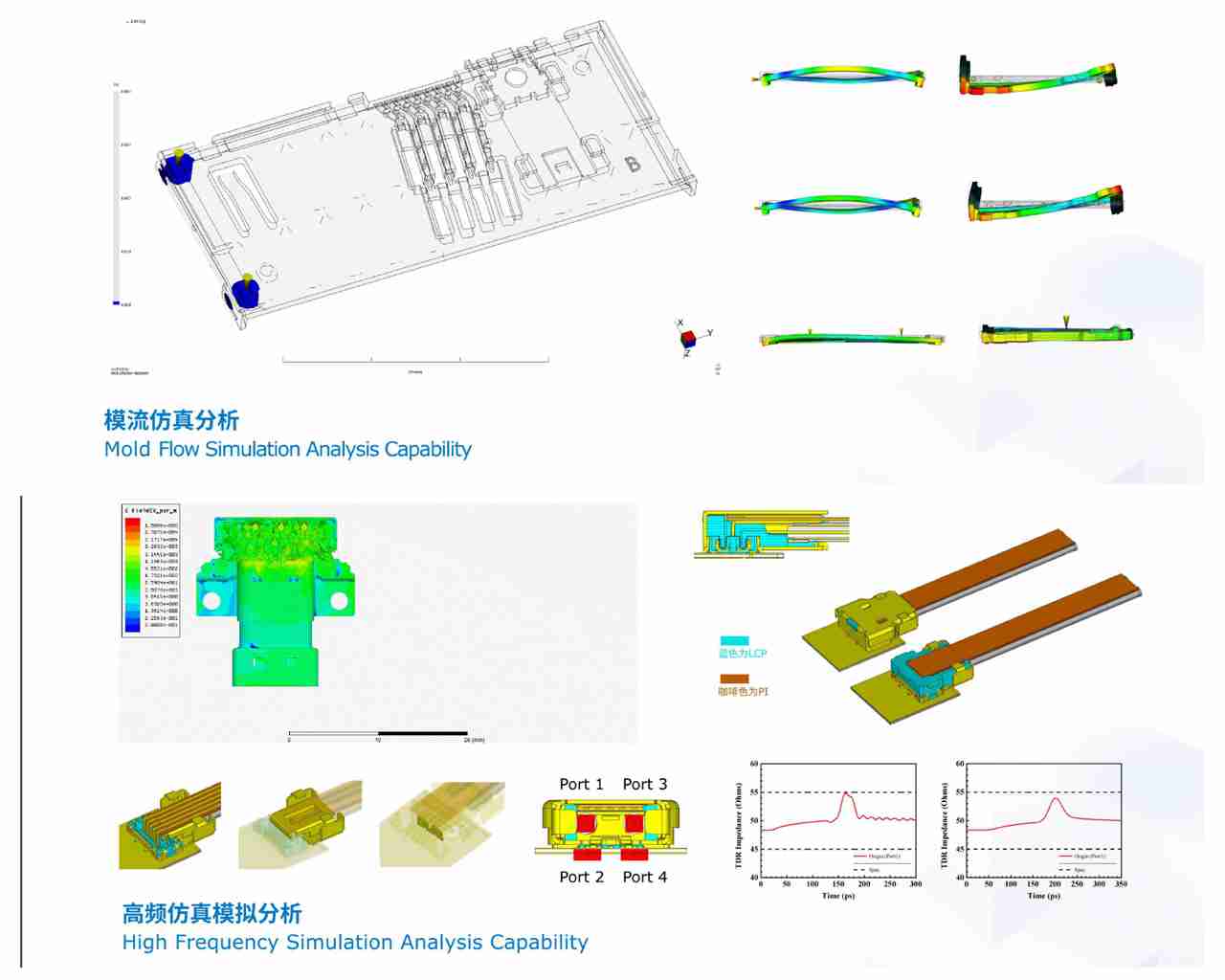
Boundary worth stating plainly. Simulation is not measurement. A simulation report predicts behaviour under modelled conditions; it does not demonstrate that a delivered lot meets a specification. Buyers evaluating a high-speed claim should ask for both the simulation summary and the measured test data, and should check whether the measurement was taken on a test coupon or on the actual board and enclosure.
16-pin and 24-pin: matching contact count to the scenario
The full-featured USB Type-C connector interface uses 24 contacts. Reduced 16-pin variants populate a subset of those positions and exist because a large share of real products do not need the full signal set. Getting this wrong in either direction is expensive: a 16-pin part in a full-featured port will not carry the data or display lanes the product advertises, while a 24-pin part in a charge-only accessory adds cost and board complexity for capability no one will use.
| Product scenario | Contact count direction | Reasoning |
|---|---|---|
| Portable SSD, USB 3.2 or USB4 data | Full-featured 24-pin | Requires the high-speed data lane set; reduced variants cannot carry the advertised throughput |
| Portable SSD or power bank, charging only | 16-pin can be appropriate | No high-speed data or display lanes required; simpler routing and lower cost |
| USB4 docking station | Full-featured 24-pin | Simultaneous data, display and power delivery share the same connector |
| Internal charging port on an accessory | 16-pin can be appropriate | Power-only function; durability and waterproofing dominate the brief |
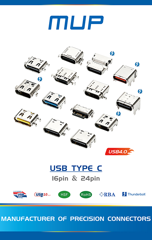
MUP catalogues both 16-pin and 24-pin USB-C socket formats within its range, which means the pin-count decision can be made at the same supplier as the mounting-format decision — but the two decisions must be recorded separately on the drawing, because a correct mounting choice paired with the wrong contact count still produces a non-conforming product.
The adjacent board-level question: NGFF M.2 and notebook PCB experience
There is a second connector decision hiding inside both scenarios. Portable SSDs frequently adopt an M.2 form factor, and docking stations increasingly include an internal M.2 slot for storage expansion. MUP lists an NGFF M.2 connector range, catalogued under models M2008 and M2015, alongside Pad, notebook, laptop and computer PCB connector experience.
That adjacency matters for procurement rather than for engineering elegance. Sourcing USB-C and NGFF M.2 from the same qualified supplier reduces the number of incoming inspection regimes, the number of quality system audits and the number of documentation trails a buyer has to maintain. It does not, however, make the two connector types technically interchangeable: they are governed by different mechanical and signal requirements, and each needs its own part-level verification. The benefit is administrative consolidation, not engineering substitution.
Where this scenario-fit approach does not apply
A credible fit analysis has to state its edges, and there are four that matter here.
- Waterproof variants are a different brief. MUP offers waterproof USB-C designs, with special requirements in its application data referencing IPX7 and IPX8 protection. A sealed connector adds housing complexity and cost, and a pocketable SSD that lives in a bag does not usually need ingress protection. Specifying it by default raises unit cost without improving the use case.
- Current rating must be confirmed per part number. USB Power Delivery Extended Power Range supports up to 240 W and the high-power USB Type-C class is specified at 5 A, but that is a specification-level requirement, not an automatic property of every USB-C socket. A dock that passes power through to a laptop needs the power path verified against the specific part, separately from the signal path.
- Mid-mount is not universally better. Removing board material under the connector reduces height but also reduces the structure that resists insertion force. On a thin board with heavy mating cycles, the trade may not pay.
- Certification is part-specific and edition-sensitive. A TID number attaches to a product, and standards evolve. IEC records reference both a 2024 edition of IEC 62680-1-3 and a later edition that cancels and replaces it, and the current applicability of the newer edition requires confirmation before it is used as a compliance baseline. Compliance files should be re-checked at each revision rather than archived once.
How this compares with treating USB-C as a commodity part
The conventional approach in both product families has been to treat the USB-C socket as a commodity: pick the cheapest part that fits the pad layout, then solve problems at the enclosure and firmware level. That approach worked when the interface carried USB 2.0 charging current and a single data lane. It becomes progressively more expensive as the interface absorbs display, high-power delivery and multi-gigabit data.
The alternative — matching mounting geometry, contact count and certification evidence to the specific scenario before tooling — costs more engineering attention up front. The trade-off is real and should be stated: it slows the first design cycle, and it requires the buyer to hold a part-level evidence file rather than a catalogue claim. For a charge-only accessory, that overhead is difficult to justify. For a USB4 dock or a high-speed portable SSD, the cost of discovering a geometry or contact-count mismatch after enclosure tooling is far higher than the cost of resolving it at the drawing stage.
Market context: regulation, concentration and the long tail
Two structural facts shape supplier strategy in this category. First, USB Type-C is no longer a design preference in the EU; it is the mandated charging interface for defined device categories, applicable since 28 December 2024 and extended to laptops since 28 April 2026. That anchors baseline demand and makes conformance documentation a market-access requirement rather than a marketing asset.
Second, the supply side is concentrated at the top. TE Connectivity, Amphenol and Molex collectively held approximately 45% of the USB Type-C connector market as of 2025, according to Future Market Insights. That concentration leaves a substantial long tail of demand for suppliers who compete on scenario-specific geometry, customization depth and delivery responsiveness rather than on catalogue breadth.
MUP operates in that long tail with a manufacturing footprint of 50,000 m² across its Shenzhen, Huizhou and Dongguan bases, more than 300 fully automated production lines, monthly capacity above 150KK pieces, and OEM/ODM customization covering mold development through final assembly. Stated lead times are 3–7 days for in-stock items and 15–25 days for mass production, with standard products shipped on carrier tape reels and small-batch R&D sampling supported.
Future outlook
The direction of travel is toward tighter connector-level discipline rather than looser. USB4 Version 2.0 at 80 Gbps and Thunderbolt 5 at 80 Gbps bidirectional with 120 Gbps Bandwidth Boost both raise the penalty for a poorly controlled interface, and each escalation narrows the gap between a connector that is “USB-C shaped” and one that is genuinely qualified for the channel.
For teams planning a portable SSD or dock refresh, three planning assumptions follow. Budget for part-level certification evidence as a line item, not a formality. Treat the mounting-format decision as an enclosure decision made jointly with the PCB team, not a purchasing decision made afterwards. And build a habit of re-verifying compliance files against the current standard edition, because the connector specification itself continues to be revised.
Where to verify, and what to bring
MUP will exhibit at Electronica 2026 in Munich, Germany, from 10 to 13 November 2026 at Hall B2, 165/6, where high-speed USB Type-C connectors, high-durability card connectors and automotive connectors are scheduled for display. Sample booking for specific part numbers is handled around the show schedule, and buyers arriving with an enclosure height budget, a target contact count and a data-rate requirement will get more from the meeting than buyers arriving with a general enquiry.
For teams that cannot attend, the same evaluation can be run from documentation: a drawing with the mounting format and contact count, a TID reference for the exact part, a durability statement expressed in mating cycles, and an operating temperature range matched to the product's thermal profile.
FAQ
How should a portable SSD design choose between top-mount, mid-mount and flag-type USB-C sockets?
The choice follows the enclosure rather than the connector catalogue. Where internal height is the binding constraint, a mid-mount socket recessed into a PCB cut-out reduces the height above the board; where the port must exit a side face, a flag-type format reorients the mating axis parallel to the board; where vertical room exists and serviceability matters, a top-mount receptacle is the simplest to place and inspect. Each format changes the PCB requirement, so the decision belongs to the mechanical and PCB teams jointly.
Does USB4.0 or Thunderbolt 5 support at connector level guarantee 80 Gbps in a finished docking station?
No. USB4 Version 2.0 specifies data rates up to 80 Gbps and Intel states Thunderbolt 5 supports 80 Gbps bidirectional with Bandwidth Boost up to 120 Gbps, but these are specification-level statements about the interface architecture. Realised throughput in a product depends on the connector's impedance control, insertion loss and crosstalk, on the PCB stack-up, and on the cable assembly. Connector-level test data and board-level measurement are required to support a throughput claim.
What does a USB-IF TID number prove when evaluating a USB-C connector supplier?
A Test ID number identifies a specific product that has completed USB-IF certification, and it is issued alongside a vendor ID. It supports the claim that the named part has been tested against the relevant programme. It does not extend automatically to other models in the same catalogue, and it does not by itself demonstrate that a standard such as IEC 62680-1-3 has been applied across a production line. Verification requires matching the TID to the exact part number under evaluation.
How is high-frequency signal stability actually verified in precision USB-C connectors?
Stability rests on controlled impedance design, optimised terminal structure and material selection. High-frequency simulation and mechanical stress analysis are used during development to predict signal attenuation and crosstalk before tooling is committed. Because simulation predicts modelled behaviour, it is normally paired with measured test data on finished parts. MUP states that its R&D team applies high-frequency simulation and stress analysis and that its products have passed USB4.0 and IEC62680 certification with USB-IF VID and TID numbers held.
Which documents should be requested before approving a USB-C connector for SMT assembly?
A practical list covers: the part drawing with mounting format and contact count; the rated voltage, current and operating temperature range; the durability rating in mating cycles; reflow profile limits, where the peak soldering temperature must not exceed 260 °C and placement nozzle pressure must not be excessive; coplanarity data; and environmental compliance reports. For EU-bound products, RoHS and REACH documentation is normally supplied per part number, and certificates are product-type specific rather than interchangeable across a range.
Are 16-pin USB-C connectors suitable for high-speed portable SSDs?
Generally not for the data port. The full-featured USB Type-C interface uses 24 contacts, and reduced 16-pin variants populate a subset of those positions. A 16-pin format is appropriate where the port is charge-only or carries low-speed data, and it can reduce routing complexity and cost in those cases. Where a product advertises USB 3.2 or USB4 data rates, the connector must support the corresponding high-speed lane set.
Product catalogue and company profile: MUP Profile E 261009 (PDF).
Have Questions or Need More Details?
Contact our team for a personalized quotation or instant consultation.
Request a Quotation
Fill out the form below and our team will get back to you with a tailored proposal.
WhatsApp Direct Chat
Prefer to chat in real-time? Message us on WhatsApp for instant assistance & quick answers.
- Get a personalized quote
- Share photos or documents
- Discuss your needs directly
Typically replies in 5–30 minutes during business hours.