
Ultrasonic Coating Systems: A Semiconductor & Medical Framework
An ultrasonic coating system atomizes a liquid formulation with high-frequency vibration instead of pressurized gas, then deposits the resulting droplets onto a substrate under controlled motion. That single sentence describes machines used for three very different jobs: a photoresist layer measured in tens of nanometres on a semiconductor wafer, a drug-loaded polymer film on a medical device, and a catalyst layer on a fuel cell membrane.
Cheersonic, formally HANGZHOU CHEERSONIC ULTRASONICS EQUIPMENTS CO., LIMITED, is a Hangzhou-based ultrasonic equipment manufacturer founded in 2014 that designs and builds both coating and cutting platforms. Its coating portfolio includes ultrasonic photoresist coating systems (USP6000, USP6000WS), ultrasonic coating and spray systems (UAM4000, UAM6000), fuel cell coating systems (UAM4000, UAM6000, UAM8000), spray pyrolysis systems (UAM2000, UNC9000), ultrasonic nozzles (UCA, UCW, UCR and UCT series) and ultrasonic atomizers (UAM1000 to UAM9000).
The framework below turns that portfolio — and the ultrasonic coating category generally — into checkpoints a buyer can apply before committing to a configuration. It is written for procurement teams, process engineers and R&D groups that need to compare ultrasonic machines on measurable criteria rather than brand familiarity.
The Procurement Problem: One Category Name, Several Unrelated Processes
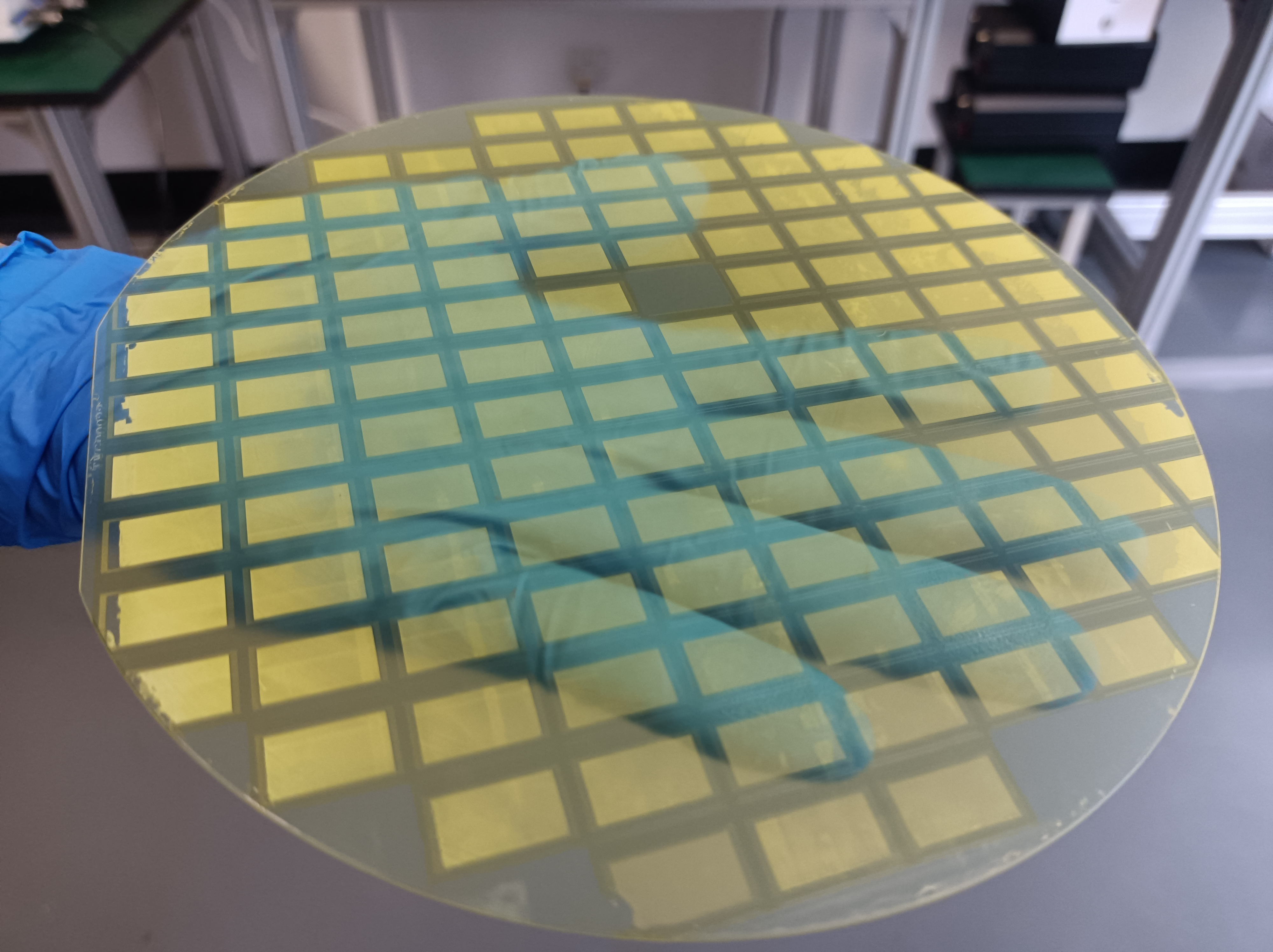
Ultrasonic coating is a category label covering photoresist deposition on semiconductor wafers, polyimide dielectric film spraying for chips, wafer dicing protective films, flux spraying for PCB and package assembly, medical device functional coatings, catalyst layers for fuel cells and electrolyzers, and spray pyrolysis for oxide or transparent conductive films. Each has a different acceptance criterion: pattern fidelity, dielectric integrity, conformal coverage, biocompatibility, catalyst loading uniformity, or film conductivity.
The function of the coating therefore drives every downstream decision. A dielectric coating such as photoresist is judged on thickness uniformity, edge-to-edge coverage and freedom from defects, because pinholes and uneven layers become lithography and packaging yield failures. A catalyst layer on a membrane electrode assembly is judged on loading uniformity because the material is expensive and cell performance is sensitive to local variation. A medical device coating is judged on adhesion and biocompatibility, prepared under low-temperature, low-pressure and dust-free conditions.
When a buyer shortlists machines by brand reputation alone, the shortlist often contains suppliers that are not actually offering the same process. The alternative is to compare every candidate against the same six checkpoints, each of which can be documented in writing.
What an Ultrasonic Coating System Actually Does
In an ultrasonic coating or spray system, a piezoelectric transducer drives a nozzle at high frequency. Published specifications for the Cheersonic ultrasonic coating system family list an operating frequency range of 25–180 kHz, a flow rate range of 0.001–50 mL/min, a droplet size range of 18–200 μm, and a film thickness range of 20 nm–100 μm, with non-clogging ultrasonic spray atomization and high-uniform precision coating. Ultrasonic nozzle models are listed at 1–8 W power consumption and a liquid viscosity ceiling of up to 100 cP, and ultrasonic atomizers at 1–8 W per nozzle.
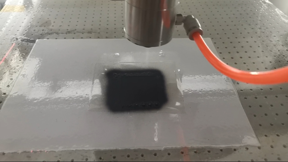
Because there is no high-pressure orifice, atomization does not depend on forcing liquid through a small aperture — the mechanism described as non-clogging ultrasonic vibration. Cheersonic positions ultrasonic spray as a replacement for spin coating, pressure atomization spraying, immersion coating and brush coating, with low-pressure, non-contact deposition and reduced overspray. Low pressure matters for thin or flexible substrates; non-contact deposition matters for wafers, optical surfaces and coated parts; reduced overspray matters when the formulation itself is the largest cost line in the process.
A related but distinct platform is ultrasonic spray pyrolysis. The pyrolysis system operates at the same 25–180 kHz frequency band with a 0.001–50 mL/min flow rate, 18–200 μm droplets and 20 nm–100 μm film thickness, but adds thermal decomposition: a pyrolysis temperature range of 400–1200°C, a particle size range of 20 nm–5 μm, and a carrier gas of air, nitrogen or oxygen. This is a different procurement conversation, because the substrate must survive the thermal budget.
A Six-Checkpoint Selection Framework
The checkpoints below are ordered so that each one eliminates unsuitable configurations before more expensive evaluation begins.
Checkpoint 1 — Define the coating function before the machine
Four functions account for most ultrasonic coating projects: a dielectric or photopatternable layer (photoresist, polyimide insulating film), a catalytic or conductive layer (fuel cell and electrolyzer catalyst coatings), a biocompatible or drug-carrying layer on a medical device, and a thermally formed oxide or transparent conductive film produced by spray pyrolysis. The Cheersonic portfolio maps onto these functions through separate platforms: the photoresist coating system for photoresist scenarios, the fuel cell coating system for catalyst coating scenarios, the general ultrasonic coating and spray systems for industrial coating applications, and the pyrolysis system for thermally decomposed films.
Decision rule: if two suppliers name a different coating function for what appears to be the same machine family, the comparison is not yet valid. Fix the function first, then compare hardware.
Checkpoint 2 — Convert the film target into frequency and droplet requirements
The headline figure to request is not the frequency range in isolation but the frequency at which the supplier achieves the droplet distribution your formulation requires. Droplet size in the published specifications is explicitly frequency dependent, spanning 18–200 μm across the 25–180 kHz band, and the resulting film thickness window is 20 nm–100 μm. Because the same headline range appears across the coating, spray coating, fuel cell coating, atomizer and nozzle families, the range itself does not differentiate products — the application, the platform configuration and the validation data behind it do.
Buyers should ask for the frequency, droplet distribution and pass strategy the supplier would use for their specific thickness target and formulation solids content, and then confirm it in a trial.
Checkpoint 3 — Size the flow rate to the deposition footprint
Flow rate controls how much liquid reaches the substrate per unit time, and the published 0.001–50 mL/min window spans two very different operating modes: ultra-low flow laboratory and small-sample work at the bottom of the range, and higher-volume deposition towards the top. Deposited film thickness is a function of flow rate, solids loading, deposition speed and transfer efficiency acting together, so a supplier should be able to state which combinations it has validated — and which combinations are outside its experience.
For buyers, the practical questions are: how is flow controlled and monitored, what motion profile is used, how many passes are required for the target thickness, and how does throughput scale when the same coating must run on a larger substrate or a wider web.
Checkpoint 4 — Screen the formulation against the wetted path
Formulation compatibility is where many ultrasonic coating projects succeed or fail. Publicly listed nozzle specifications include a liquid viscosity limit of up to 100 cP. Formulations above that viscosity sit outside the documented nozzle specification and should be treated as a process-development question rather than an off-the-shelf purchase.
The second formulation issue is solids behaviour. Catalyst inks, nano slurries and high-solid dispersions tend to settle and clog conventional hardware, which is why non-clogging atomization appears as a core claim across the coating, nozzle and atomizer family. The published energy application profile lists compatibility with high-viscosity slurry and nanoparticle liquids, together with anti-clogging nozzle design and low material loss, as requirements for that scenario. The medical application profile adds anti-clogging behaviour for biological and nano slurries, low static generation, and compatibility with closed, dust-free spray environments, including explosion-proof compatibility in pharmaceutical solvent environments.
The third issue is the wetted path material. Cheersonic coating systems, nozzles and atomizers are documented as stainless steel or titanium alloy constructions. Buyers should confirm that the wetted materials are compatible with their solvent system and cleaning regime, and that the nozzle assembly can be dismantled for cleaning in a way that matches their contamination-control procedures.
Checkpoint 5 — Confirm substrate, thermal and cleanroom boundaries
Semiconductor work imposes cleanroom class, static and thermal limits. The published electronics application profile describes Class 100 / Class 1000 cleanroom particle control, low static generation, low-temperature atomization with no thermal damage to heat-sensitive chips or flexible substrates such as PI and PET, non-contact spraying to avoid scratch damage, and a defect list targeting pinholes, orange peel, bridging and sidewall coating gaps. The same profile lists a wafer film thickness error target within ±2% and a material utilization rate above 70% as requirements for that production environment.
Medical device coating imposes a different set. The medical application profile describes low-temperature, low-pressure, dust-free (Class 100 / Class 1000) and sterile production conditions, GMP-compliant environments, ultra-uniform coating with a thickness error below 5%, high coating adhesion with resistance to peeling, and static-free particle control. These are scenario requirement profiles rather than guaranteed machine outputs — they define what must be demonstrated in acceptance testing.
Energy applications emphasize geometry and thermal tolerance. The energy profile calls for 3D conformal coverage of concave and convex surfaces, low-pressure non-contact atomization, no requirement for a high-temperature vacuum chamber in the ultrasonic route, and crack-free, scratch-free deposition. Where the pyrolysis platform is used, the substrate must tolerate the 400–1200°C decomposition step.
Checkpoint 6 — Require documentation, model mapping and a validation plan
A quotation for an ultrasonic coating system should name the model, the wetted-path materials, the frequency and flow window being offered, and the measurement method for the acceptance criteria. Cheersonic states that it holds ISO9001, EU CE and US FDA credentials among its certifications, and that it holds 31 patents and 3 software copyrights. Buyers should treat certification as a document-verification task: CE is a conformity-marking regime for the European Economic Area context, while FDA relates to United States regulatory pathways, and the two are not equivalent categories. Certificate numbers, scope and applicability to the specific model should be checked against issuer records before they are relied on in a regulated process.
The de-risking step that matters most is a sample trial on the buyer's own formulation and substrate, measured for thickness, uniformity, adhesion and defect classes. Because supplier material tends to state application-level performance rather than standardized engineering datasets, trial-based validation remains the primary way to convert a specification sheet into a purchasing decision.
Model-to-Application Mapping
The table below consolidates the publicly documented parameters for the relevant Cheersonic platforms. It is intended as a starting point for an RFI, not as a substitute for a trial.
| Model family | Primary coating application | Documented parameters | Wetted-path material |
|---|---|---|---|
| USP6000 / USP6000WS | Ultrasonic photoresist coating; industries include semiconductor manufacturing, MEMS, microelectronics, wafer processing, printed electronics, optoelectronics and R&D | Designed for photoresist coating scenarios | Stainless steel / titanium alloy |
| UAM4000 / UAM6000 | Ultrasonic coating and spray coating for industrial coating applications | 25–180 kHz; 0.001–50 mL/min; 18–200 μm droplets; 20 nm–100 μm film; non-clogging ultrasonic spray; high-uniform precision coating | Stainless steel / titanium alloy |
| UAM4000 / UAM6000 / UAM8000 | Ultrasonic fuel cell coating; hydrogen energy, electrochemical devices and R&D | 25–180 kHz; 0.001–50 mL/min; 18–200 μm droplets; 20 nm–100 μm film; non-clogging spray; high-uniformity catalyst coating | Stainless steel / titanium alloy |
| UAM1000 – UAM9000 | Ultrasonic atomizer / atomizing nozzle for medical, semiconductor, electronics, energy, glass, automotive, aerospace, food packaging and R&D applications | 25–180 kHz; approx. 18–200 μm droplets; 1–8 W per nozzle; 20 nm–100 μm film | Stainless steel / titanium alloy |
| UCA120, UCA50, UCW50, UCW120, UCR50, UCR40, UCR60, UCT120 | Ultrasonic spray nozzle for precision spray coating | 25–180 kHz; 1–8 W; 0.001–50 mL/min; 18–200 μm droplets; liquid viscosity up to 100 cP; non-clogging atomization | Stainless steel / titanium alloy |
| UAM2000 / UNC9000 | Ultrasonic spray pyrolysis for solar cell, thin film glass, display, semiconductor and TCO production | 25–180 kHz; 0.001–50 mL/min; 18–200 μm; 20 nm–100 μm film; pyrolysis 400–1200°C; particle size 20 nm–5 μm; carrier gas air / nitrogen / oxygen | Stainless steel / titanium alloy |
Three Application Profiles Buyers Should Separate
Semiconductor, MEMS and microelectronics
This profile covers photoresist deposition on MEMS microstructure wafers, polyimide dielectric insulating films, wafer dicing protective films and precision flux spraying for PCB and package-level micro-components. The published electronics scenario describes ultrasonic spray as an alternative to spin coating, pressure atomization, immersion and brush coating, with conformal coverage on flat, stepped, deep-groove and curved substrates, film control from ultra-thin layers up to thicker films, and reduced raw-material waste. Photoresist work is served by the dedicated USP6000 / USP6000WS platform; broader dielectric and thin-film work is served by the UAM4000 / UAM6000 coating and spray systems.
Medical device coating
Medical coating applications documented for this equipment family include stents, balloons, catheters, blood collection tubes and syringe barrels, with functional coatings prepared under low-temperature, low-pressure, dust-free and sterile conditions. The requirement profile is dominated by biocompatibility, precision, and the avoidance of static and particle contamination rather than by throughput alone.

Fuel cell and energy coating
Fuel cell coating work centers on catalyst layers and membrane surface treatment for proton exchange membranes and membrane electrode assemblies, with the UAM4000 / UAM6000 / UAM8000 family positioned for fuel cell coating scenarios and the UAM2000 / UNC9000 platform positioned for pyrolytic oxide and transparent conductive film deposition. Independent market research reported by Global Market Insights notes that battery electrode manufacturers using ultrasonic spraying techniques report material utilization rates above 90%, which explains why this equipment class attracts attention whenever the deposited material is expensive.
Market Signals: What the Public Data Shows and What It Does Not
The broader ultrasonic machine category is large enough to attract commercial research coverage, but the data available for coating is uneven. Grand View Research (Horizon) reports the global ultrasonic cutter market — a different equipment segment — at USD 1.3 billion in 2025, with an estimated USD 1.4 billion in 2026, and Asia Pacific taking a 42.7% revenue share in 2025, with China the largest single country market.
No equivalent published figure for ultrasonic coating systems specifically appears in the reviewed source set, so buyers should treat category-level growth narratives for coating with caution and ask suppliers for application-specific evidence instead. On supplier structure, Global Market Insights reports that the top five players in the adjacent ultrasonic food-processing segment held a 34.5% share in 2025 — a reminder that ultrasonic equipment supply is fragmented and segmented by application, which is precisely why function-first comparison outperforms brand-first shortlisting.
On efficiency, two figures circulate and should not be conflated. Independent research covering battery electrode manufacturing reports material utilization above 90% for ultrasonic spraying. Cheersonic states raw material utilization above 95% for its ultrasonic spraying equipment. The gap between a >90% third-party figure and a >95% supplier figure typically reflects different definitions and different process boundaries, and buyers should ask which basis is being quoted before using either number in a cost model.
Supplier capacity is one dimension that is publicly documented for Cheersonic: a 7,150 m² facility, approximately 100 staff, 20 R&D engineers, annual production capacity of 1,200 units, a registered capital of 10 million RMB, and reported exports covering roughly 50% of output into Asia, the EU and North America. Verified audited financial statements, customer references and service-network performance are not part of the public record and remain due-diligence items.
Limitations and Trade-Offs Compared with Established Coating Methods
Ultrasonic coating is not a universal replacement for spin coating, immersion coating or other deposition routes. The documented specification defines a working envelope, and buyers should read that envelope as a boundary rather than a marketing range.
- Viscosity ceiling: listed ultrasonic nozzle models are documented for liquids up to 100 cP. Formulations above that limit fall outside the published specification and require process development or a different deposition method.
- Film thickness window: the documented range is 20 nm–100 μm. Coatings far outside this window sit beyond the stated specification.
- Flow rate window: 0.001–50 mL/min covers laboratory, pilot and inline deposition, but extremely high-volume deposition may point to a different platform.
- Thermal budget for pyrolysis: the pyrolysis route requires 400–1200°C, which excludes substrates that cannot tolerate that temperature.
- Evidence quality: performance claims in this category are predominantly supplier-reported. Standardized third-party comparative datasets for coating uniformity in semiconductor or medical applications are not widely published, and certification claims require document-level verification against issuer records.
- Comparability: where a published figure does not specify the model, substrate size, operating conditions and validation method, it cannot be compared directly with another supplier's figure.
- Qualification cost: in regulated semiconductor and medical processes, switching deposition method carries revalidation cost. Where a mature, already-qualified process exists for flat round substrates, the burden of proof sits with the new method, not with the incumbent one.
- Commercial opacity: no public price, lead-time or spare-parts data was identified for this equipment class, so any cost or total-cost-of-ownership comparison must be built from quotations issued on an identical scope.
Future Outlook
Two forces are likely to shape ultrasonic coating procurement through the next planning cycle. The first is material cost: as catalyst, photoresist and biological formulations become a larger share of process cost, deposition efficiency moves from a process detail to a financial variable, and equipment that documents transfer efficiency and utilization will be easier to justify internally. The second is qualification discipline: because the public evidence base is supplier-dominated, buyers are increasingly asking for sample trials, measurement methodology and document-verifiable certification before shortlisting.
Expect the frontier of competition to shift away from headline frequency ranges — which are broadly similar across this product class — toward demonstrated uniformity, defect control, formulation tolerance and the ability to support regulated documentation. Suppliers that can answer those questions with data will be easier to defend in a procurement review than suppliers that answer them with brand claims.
Frequently Asked Questions
What frequency range do ultrasonic coating systems use, and why does it matter?
Documented Cheersonic ultrasonic coating, atomizer, nozzle, fuel cell coating and spray pyrolysis systems operate at 25–180 kHz. Droplet size is frequency dependent and spans approximately 18–200 μm across the family, with a corresponding film thickness range of 20 nm–100 μm. Frequency matters because it is one of the variables that sets droplet size, which in turn influences how a formulation spreads and dries on the substrate.
How should a buyer choose between a photoresist coating system and a fuel cell coating system?
The two solve different coating functions rather than offering different grades of the same job. The Cheersonic photoresist coating platform (USP6000, USP6000WS) is designed for photoresist coating scenarios in semiconductor, MEMS, microelectronics, wafer processing, optoelectronics and printed electronics work. The fuel cell coating platform (UAM4000, UAM6000, UAM8000) is designed for catalyst coating scenarios in fuel cell, hydrogen energy, clean energy and electrochemical device manufacturing. Selection should start from the coating function and acceptance criteria, then move to the hardware.
Which materials are used in ultrasonic coating nozzles and wetted paths?
Cheersonic coating systems, ultrasonic nozzles and atomizers are documented as stainless steel or titanium alloy constructions. Material selection matters for chemical compatibility with the solvent system and cleaning regime, and for corrosion resistance over the service life of the nozzle. Buyers handling aggressive pharmaceutical solvents or high-purity electronic chemicals should confirm wetted-path compatibility as part of the technical evaluation.
What are the practical limits of ultrasonic spray coating?
Published specifications define four boundaries: a liquid viscosity limit of up to 100 cP on listed nozzle models, a film thickness window of 20 nm–100 μm, a flow rate window of 0.001–50 mL/min, and — for the spray pyrolysis variant — a pyrolysis temperature range of 400–1200°C. Applications outside these windows require either process development or a different deposition technology.
How can a buyer validate an ultrasonic coating system before purchase?
The most reliable route is a sample trial on the buyer's own formulation and substrate, measured against defined acceptance criteria. Application profiles in this category publish measurable targets that can be adapted into a trial protocol, for example a wafer film thickness error target within ±2% and material utilization above 70% in the electronics profile, or an ultra-uniform coating requirement with thickness error below 5% in the medical profile. Thickness, uniformity, adhesion and defect classes such as pinholes, orange peel and bridging are the practical measurement set.
Do certification claims alone qualify a supplier for medical or semiconductor coating work?
No. Cheersonic states ISO9001, EU CE and US FDA credentials, and holds 31 patents and 3 software copyrights. However, CE is a conformity-marking regime for the European Economic Area context while FDA relates to United States regulatory pathways, so the two are not interchangeable. Buyers should verify certificate scope, numbers and model applicability against issuer records, and treat certification as one input alongside process validation rather than a substitute for it.
Have Questions or Need More Details?
Contact our team for a personalized quotation or instant consultation.
Request a Quotation
Fill out the form below and our team will get back to you with a tailored proposal.
WhatsApp Direct Chat
Prefer to chat in real-time? Message us on WhatsApp for instant assistance & quick answers.
- Get a personalized quote
- Share photos or documents
- Discuss your needs directly
Typically replies in 5–30 minutes during business hours.