{{ variable.name }}
| Type | Custom Hydraulic Cylinder Telescopic Hydraulic Cylinder Multi-Stage Hydraulic Cylinder Single-Acting Telescopic Cylinder Double-Acting Telescopic Cylinder Front-Mount Telescopic Cylinder Underbody Telescopic Cylinder Ejector Telescopic Cylinder | Model | APEX-CTC Series |
| Params | Cylinder Structure: Multi-stage telescopic construction Acting Type: Single Acting or Double Acting Number of Stages: Customized according to required stroke and available retracted length Largest Stage Diameter: Engineered according to required initial lifting force and working pressure Intermediate Stage Diameters: Progressively sized according to load curve and structural requirements Final Stage Diameter: Determined according to final-stage load, stability and mounting requirements Total Stroke: Customized according to the required equipment movement Stage Stroke Distribution: Engineered according to total stroke, overlap and stability requirements Retracted Length: Minimized according to the number of stages and installation envelope Extended Length: Determined by retracted length and total effective stroke Stroke-to-Retracted-Length Ratio: Optimized according to the equipment installation space Working Pressure: Customized according to the approved hydraulic-system specification Maximum System Pressure: Must be confirmed before final engineering approval Proof-Test Pressure: Defined in the approved inspection and testing plan Initial Lifting Force: Calculated from the effective area of the largest stage and working pressure Stage Output Force: Calculated separately for each telescopic stage Load Curve: Must be evaluated throughout the complete tipping, lifting or ejecting cycle Operating Direction: Vertical, inclined or application-specific installation Return Method: Gravity return, external load return or hydraulic power return Extension Sequence: Largest stage to smallest stage unless otherwise specified by the approved design Retraction Sequence: Smallest stage to largest stage unless otherwise specified by the approved design Stage Overlap: Engineered to maintain structural stability and guide support Side-Load Condition: Telescopic cylinders must be protected from excessive side loading Maximum Dump or Lift Angle: Determined by equipment geometry rather than by cylinder stroke alone Operating Speed: Selected according to stage displacement, oil flow and stability requirements Hydraulic Flow Requirement: Calculated according to cylinder displacement and required cycle time Hydraulic Medium: Mineral-based hydraulic oil or approved compatible fluid Operating Temperature: Determined by the selected seals, hydraulic fluid and operating environment Hydraulic Port: SAE ORB, NPT, BSPP, metric thread, flange or customer-specified connection Port Position: Customized according to hose routing and mounting orientation Base Mounting: Trunnion, cross-tube, ball, clevis, flange or custom mounting Rod-End Mounting: Ball, pin-eye, clevis, spherical bearing or custom mounting Trunnion Position: Customized according to equipment geometry and tipping-force analysis Bleed Port: Optional according to installation orientation and hydraulic-circuit requirements Load-Holding Protection: Optional counterbalance valve, pilot-operated check valve or hose-burst valve External Limit Device: Optional stroke limiter, safety cable or mechanical stop provision Position Monitoring: Optional external stroke sensor or application-specific position-monitoring system Surface Protection: Industrial paint or corrosion-resistant coating selected for the operating environment Identification: Customer part number, serial number, logo and traceability code available Testing: Dimensional inspection, pressure testing, leakage testing, stage-sequence testing and full-stroke cycling Documentation: Approved drawing, dimensional report, test report and inspection records available | Material | Outer Cylinder Tube: High-strength seamless steel tube selected according to pressure and structural requirements Telescopic Stages: Precision-machined high-strength seamless steel tubes Final Stage / Plunger: High-strength steel with application-specific surface treatment Cylinder Base: High-strength forged, cast or machined steel Trunnion Components: High-strength alloy or structural steel Rod-End Ball or Eye: High-strength forged or machined steel Stage Guides: High-load, low-friction composite bearing materials Wear Rings: Reinforced polymer, phenolic composite or application-specific bearing material Dynamic Seals: High-pressure polyurethane or application-specific telescopic sealing system Static Seals: NBR, FKM or temperature-specific elastomer Stage Wipers: Heavy-duty polyurethane or application-specific scraper configuration Retaining Components: High-strength alloy steel Welded Components: High-strength weldable structural steel Surface Coating: Industrial coatin |
| Applicable Industry | Dump Trailer Manufacturing Dump Truck Manufacturing Agricultural Tipping Trailers Mining and Quarry Equipment Waste and Recycling Equipment Refuse Collection Vehicles Material Handling Equipment Mobile Compactors Construction Equipment Special-Purpose Vehicles Forestry Equipment Industrial Lifting Systems | ||
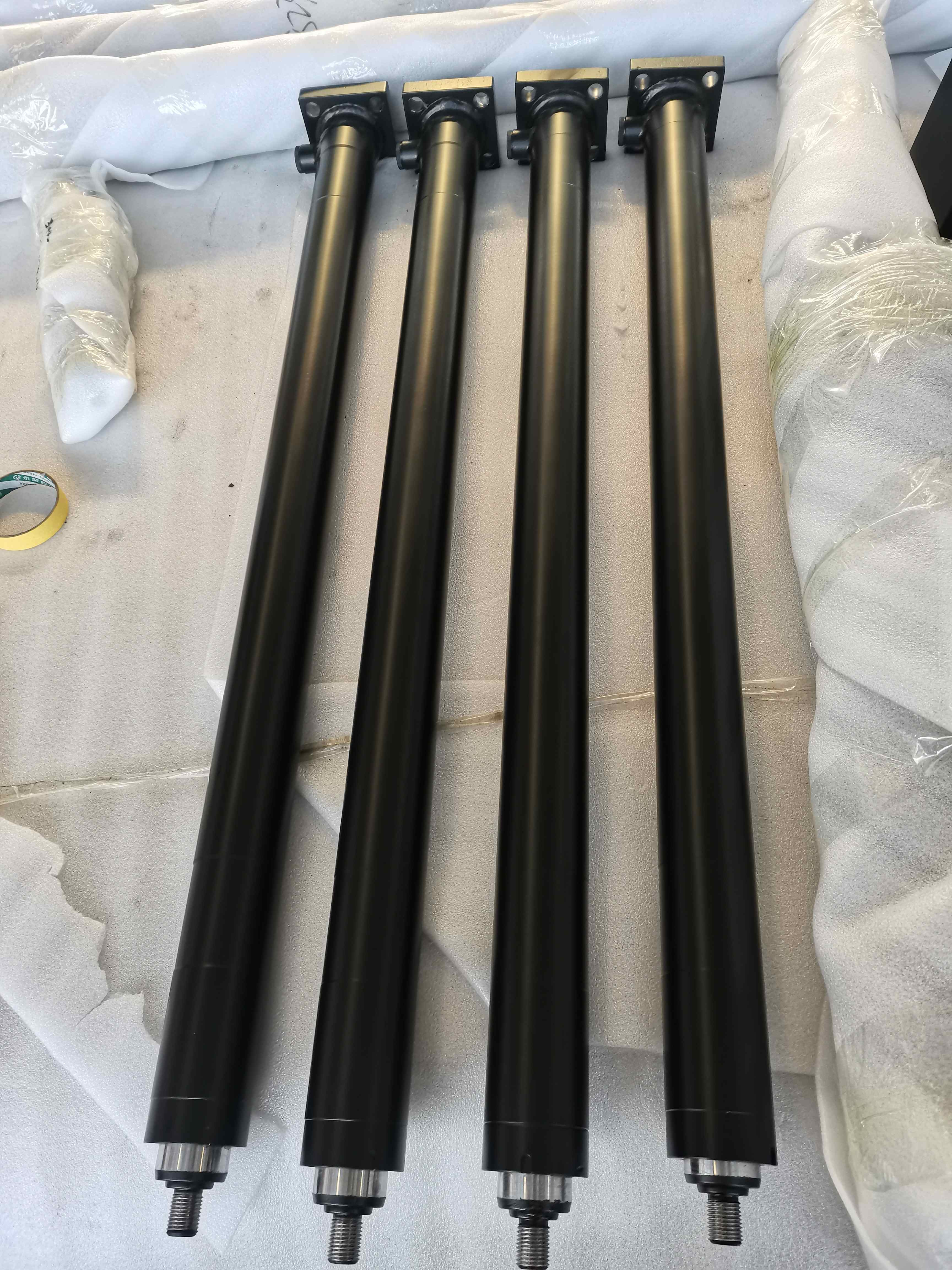
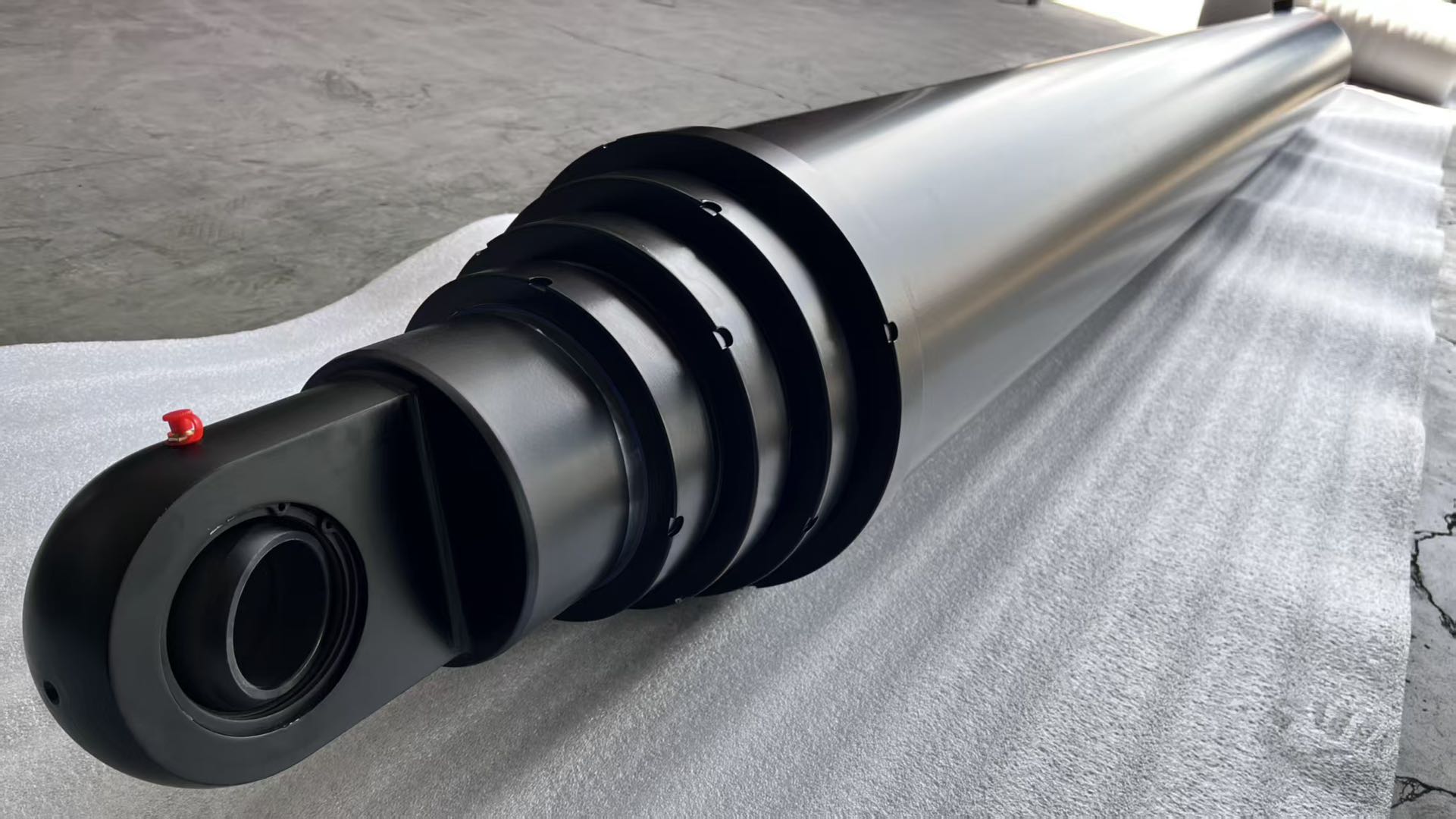
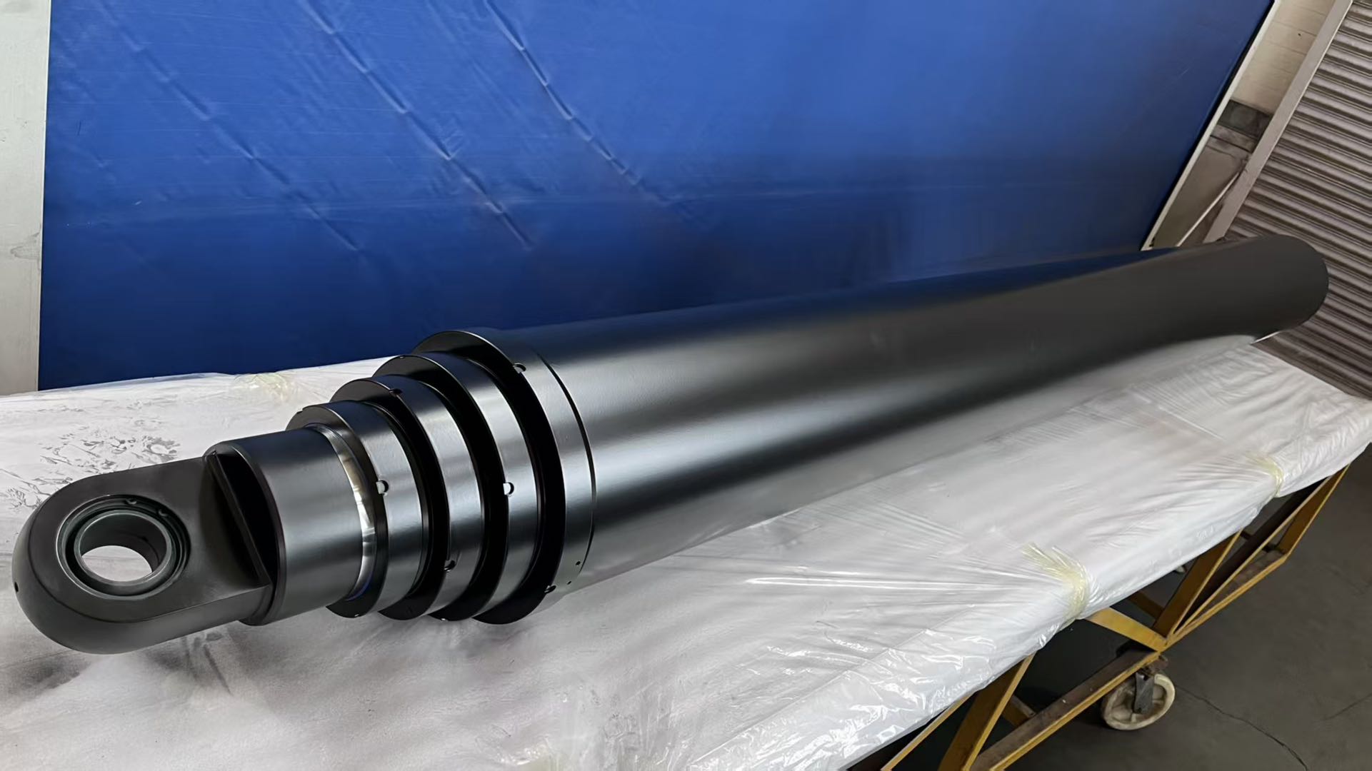
Provides a long working stroke from a compact retracted envelope. Available in single-acting gravity-return and double-acting power-return configurations. The number of stages, stage diameters and stroke distribution can be customized for the actual equipment. Each stage’s output force can be matched to the changing load throughout the lifting cycle. Front-mount, underbody, trunnion-mounted and application-specific configurations are available. Custom mounting geometry supports different dump-body lengths, hinge positions and lifting angles. Heavy-duty stage guides improve alignment and extension stability. Application-specific sealing and wiper systems protect the cylinder in dusty, muddy and outdoor environments. Optional load-holding protection improves safety during lifting and load retention. Stage extension and retraction sequences are functionally tested before shipment. Replacement cylinders can be manufactured from an approved drawing, sample or verified installation dimensions. Custom paint, identification, ports and mounting interfaces support OEM trailer and vehicle programs.

apex-double-acting-telescopic-hydraulic-cylinder

apex-custom-multi-stage-hydraulic-cylinder-range

apex-custom-telescopic-hydraulic-cylinder