
Metrology 3D Scanner vs. Caliper vs. LiDAR: A Buyer's Decision Matrix
A caliper, a metrology 3D scanner and a LiDAR system often end up on the same procurement shortlist, as though they were three grades of the same instrument. They are not. Each produces a different kind of measurement record, and the correct choice depends on what the factory intends to do with that record after the measurement is finished.
The decision in one paragraph. Use a caliper where a single accessible dimension must be verified quickly and no digital record is required. Use a metrology 3D scanner where the part has freeform surfaces, many features, or a traceability obligation, and where full-surface data must be stored, shared and re-compared against CAD over time; on those tasks optical scanning measures up to 5 to 10 times faster than a caliper and captures millions of points per scan instead of a few discrete points. Use LiDAR where the object of interest is an environment or a very large area measured in meters to tens of meters, and where millimeter-level accuracy is sufficient.
The Decision Matrix in Full
The rows that decide a purchase are rarely the accuracy row on its own. They are the rows about what data exists after the measurement, who else in the organisation can use it, and how the next part will be compared with this one.
| Criterion | Caliper | Metrology 3D scanner | LiDAR |
|---|---|---|---|
| Measurement principle | Contact, manual, point to point | Non-contact optical, laser line or structured light, full surface | Laser-based long-range spatial mapping |
| Data produced | A few discrete measurement points, one dimension at a time | Millions of points per scan, full-surface point cloud and mesh | Spatial position of surfaces across a large area or site |
| Speed on a full-surface task | One separate operation per feature | Up to 5 to 10 times faster than caliper measurement and inspection | Efficient for large-area coverage |
| Geometry fit | Simple, accessible outer and inner dimensions | Complex and curved surfaces, freeform geometry, many features | Environment-scale surfaces, sites, infrastructure |
| Accuracy class | Depends on the tool and the operator technique; no 3D record | Sub-millimeter measurement accuracy, certified against optical metrology standards | Millimeter accuracy is normal, over meter to tens-of-meters ranges |
| Operating environment | Anywhere | Generally requires calibration and controlled conditions for precision measurement | Better suited to outdoor and large-area deployment |
| Digital record | Manual documentation | Native digital storage, sharing, repeatability and traceability | Digital spatial dataset of the scanned area |
| Where it fits | Single dimensions, quick bench and incoming checks | Industrial inspection, dimensional measurement, reverse engineering, quality control, precision manufacturing | Surveying, autonomous navigation, large-area mapping, construction site mapping, infrastructure monitoring |
| Main limitation | No full-surface data and no 3D model; each feature needs its own operation | Materially higher acquisition cost than a caliper; needs calibration discipline and controlled conditions | Less emphasis on fine surface detail, so it is a weak fit for dimensional inspection of machined features |
Caliper: Fast for One Dimension, Silent on the Rest
A caliper answers a point-to-point distance question, and it answers it immediately. For an accessible outer or inner dimension on a single part, nothing on this list is quicker to deploy. That is why the tool survives every metrology upgrade cycle.
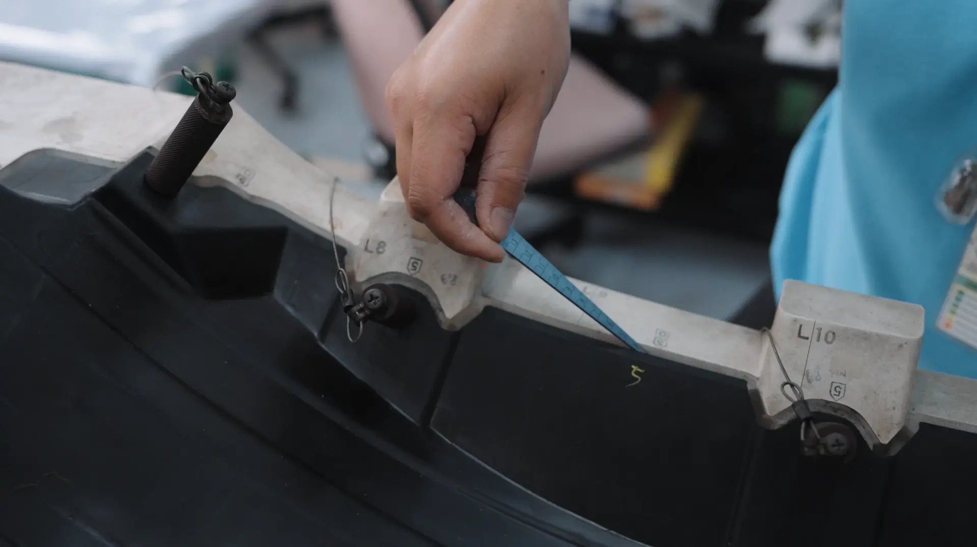
The problem appears when the part stops being simple. A caliper measures point-to-point distance only. Every additional feature needs its own operation, its own fixturing decision and its own note in the inspection sheet. On a part with dozens of dimensions, freeform surfaces or blended radii, coverage stops being a measurement question and becomes a labour question. Nothing in the caliper workflow produces a surface model, so there is no artifact that can be re-compared against CAD when the drawing changes or when a supplier disputes a deviation six months later.
Because it is a contact method, there is also a handling consideration on soft, polished or thin-walled parts. The caliper stays the right tool for incoming spot checks, quick pass or fail decisions and field work where no digital record is required. It becomes an expensive bottleneck when the same measurement must be documented, repeated and archived.
What a Metrology 3D Scanner Actually Changes
3D scanning is a non-contact technology that captures an object's geometric data to build a precise digital model. It projects structured light or laser beams onto the surface, receives the reflected signal and calculates the position of each captured point; the resulting data is converted into a 3D model used for inspection, design and production.
Against a caliper, the differences that matter at the decision stage are specific. Optical scanning is up to 5 to 10 times faster on full-surface measurement and inspection, because it captures millions of data points per scan instead of a handful of discrete points. It handles complex and curved surfaces that a two-jaw tool cannot address geometrically. There is no physical contact and therefore no wear on the workpiece. And because the output is already digital, data storage, sharing, repeatability and traceability are easier to operate than a paper inspection sheet.
The record is also more useful downstream. A typical inspection workflow runs from 3D data acquisition to processing and alignment, then CAD comparison, deviation analysis, dimensional inspection and GD&T evaluation, and finally automated report generation. That sequence is what converts a measurement into a quality document, and it is the real product a metrology buyer is purchasing.
LiDAR: Coverage Over Detail
LiDAR is not a slower 3D scanner. It is designed for long-range spatial mapping and environment sensing, which is a different task from surface inspection. A metrology 3D scanner is built for high-precision 3D measurement and detailed surface capture; LiDAR is optimised for meter to tens-of-meters measurement ranges and large-area spatial coverage, where millimeter measurement accuracy is normal.
That positioning explains its application list: surveying, autonomous navigation, large-area mapping, construction site mapping and infrastructure monitoring. It also explains why LiDAR is described as better suited to outdoor and large-area deployment, with less emphasis on fine surface detail. Where a shop-floor scanner has to resolve a machined radius, LiDAR has to cover a site.
The cost logic runs in parallel. Metrology 3D scanning is positioned as an affordable equipment cost for precision measurement, while LiDAR is cost-effective for large-area scanning and mapping. A buyer who compares them on purchase price alone will usually conclude that LiDAR covers more area per unit of spend, and that conclusion holds until the first deviation map on a machined surface is required. The trade-off is coverage against depth of detail, and it does not resolve in favour of one instrument.
Where the Matrix Says: Not This Tool
A comparison that only lists advantages is not a decision document. The boundaries below are the ones that most often cause a metrology scanner to fail an acceptance test after purchase.
- Calibration and environment. A 3D scanner generally requires calibration and controlled conditions for precision measurement. Portable and wireless designs reduce the constraint on where the work happens; they do not remove the need for calibration discipline.
- Acquisition cost. Against a caliper, the scanner is in a different cost class entirely. The comparison data behind this article describes the gap bluntly: scanning is a substantially more expensive route to the same nominally simple question, and that only pays back when coverage, speed or traceability actually matter to the business.
- Micro-detail on very small parts. Fixed blue structured light delivers the highest detail on small objects, but that route may require surface preparation to capture micro-features reliably.
- Access and occlusion. Deep holes, narrow gaps and hidden blind spots may not be reachable by a laser line. In those geometry cases a portable probe paired with the scanning system is the usual workaround rather than a specification change.
- Volumetric error on large structures. Scanning error accumulates with part size. On objects of several meters to tens of meters, photogrammetry or global marker frameworks are introduced to control global accuracy, which adds a workflow step that a single-component buyer does not need.
One commonly assumed limitation does not hold universally. Dark or highly reflective surfaces can be handled by advanced blue laser and infrared light sources without scanning spray, which removes surface preparation from many production parts.
Reading Accuracy Claims Correctly
Four different numbers sit behind the single word accuracy, and buyers who collapse them lose the ability to compare suppliers fairly.
- Accuracy is how closely a measured result matches the true dimension. A 100.00 mm feature measured as 100.02 mm carries an error of 0.02 mm.
- Precision, or repeatability, is how consistently the same measurement is reproduced. Five consecutive scans reading 100.02, 100.02, 100.03, 100.02 and 100.02 mm vary by 0.01 mm, which indicates high precision even though the results sit slightly off the true value.
- Resolution is the smallest detail the scanner can distinguish. Higher resolution does not automatically mean higher accuracy: a system can capture extremely fine detail and still introduce dimensional error.
- Volumetric accuracy describes error across larger volumes. With a specification written as 0.02 mm plus 0.015 mm per meter, measuring a 2-meter object gives 0.02 + (0.015 x 2) = 0.05 mm as the maximum measurement error over the full length.
| Accuracy tier | Typical requirement | Scanner form that fits |
|---|---|---|
| 0.005 to 0.02 mm | Functional safety parts, strict GD&T inspection, precision reverse engineering | Fixed blue structured light with high-resolution cameras, for example OptimScan Q12/Q9 HD at 0.004 mm accuracy |
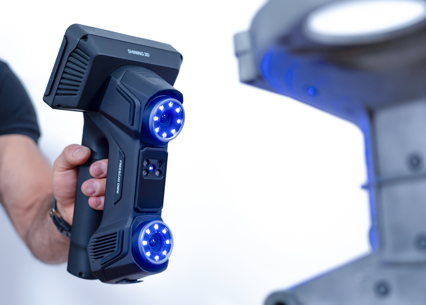
| 0.02 to 0.05 mm | Assembly verification and structural analysis | Handheld systems, for example FreeScan Omni at 0.02 mm accuracy |
| 0.05 to 0.1 mm | Overall deformation analysis, surface deviation mapping, large cosmetic parts | Tracking systems, for example FreeScan Trak Nova at 0.02 mm accuracy |
Standards are how those numbers become comparable across suppliers. VDI/VDE 2634 Part 3 is the primary standard for evaluating the accuracy of optical 3D measuring systems based on area scanning. The ISO 10360 series governs acceptance and reverification testing, with ISO 10360-12 addressing articulated arm coordinate measuring machines specifically. ISO/IEC 17025 accreditation matters because it is the verification requirement for laboratories publishing 3D scanner accuracy data. A scanner whose accuracy claims are not traceable to an accredited laboratory is a claim, not a specification.
A Four-Step Procurement Sequence
The sequence below reduces a crowded market to a shortlist before any demonstration is booked.
Step 1, object size. Small parts under roughly 500 mm need systems built to capture intricate cavities and fine geometry. Medium to large components between roughly 500 mm and 2,500 mm involve complex surfaces, multiple textures and large curved areas that call for portable scanning. Structures beyond roughly 2,500 mm need an expansive tracking volume to hold consistency across the part.
Step 2, accuracy tier. Use the three tiers in the table above. Specifying tighter accuracy than the drawing requires adds cost without adding acceptance value.
Step 3, workflow and environment. Wireless and standalone operation matters on complex shop floors and elevated platforms where cables restrict movement. Marker-free dynamic tracking removes preparation time on parts where markers are impractical. Material adaptability, access to deep features and overall cycle time belong in the same review.
Step 4, verification. Ask which standard the accuracy claim is tested against, which laboratory produced the data, and whether that laboratory holds ISO/IEC 17025 accreditation. This is the step that separates a metrology purchase from an equipment purchase.
How SHINING 3D Maps to This Decision
SHINING 3D (Shining 3D Tech Co., Ltd.), founded in 2004 and headquartered in Hangzhou, China, is a 3D vision technology company that develops high-precision 3D scanning hardware and software for metrology, professional engineering, dental and entry-level applications. The company reports a 140,000 square meter facility, 1,367 employees including 533 engineers, more than 330 authorized patents and more than 230 software copyrights, with subsidiaries in Stuttgart, Barcelona, California, Florida and Tokyo and an export share of around 70% across EU, USA and APAC markets.
For the three-tier structure above, the portfolio maps directly. OptimScan Q12/Q9 HD is a fixed blue structured light inspection scanner with 0.004 mm accuracy, high-resolution cameras and dual scanning ranges, aimed at small-object quality inspection and restoration. FreeScan Omni is a wireless, standalone metrology handheld scanner at 0.02 mm accuracy, using blue laser for complex dark and reflective surfaces and running a scan-to-inspection workflow on the device itself. FreeScan Trak Nova is a wireless multi-functional dynamic tracking and scanning system for markerless capture of medium to large objects at 0.02 mm, with a detachable handheld scanner; its tracker, FreeScan UE Nova, also operates as a handheld laser scanner. All three are stated as certified to VDI/VDE 2634 Part 3 and ISO 10360.
Verification infrastructure is the part of the offer that answers Step 4. The company operates a precision laboratory accredited to ISO/IEC 17025 for independent dimensional calibration and inspection, and maintains ISO 9001, ISO 14001, ISO 45001 and ISO 13485 management system certification alongside CE, FDA and FCC product compliance, AEO supply-chain status and TISAX, ISO/IEC 27001, 27701, 27017 and 27018 information security certification.
On commercial positioning, the company compares its own portfolio against established metrology brands on the basis of a broader model range covering handheld, fixed and tracking formats, and states that for comparable applications and configurations its products can be approximately 10% lower in price. Those figures originate from the manufacturer's comparison documentation and should be validated against a specific quotation during evaluation.
Application Fit: Where the Choice Is Decided in Practice
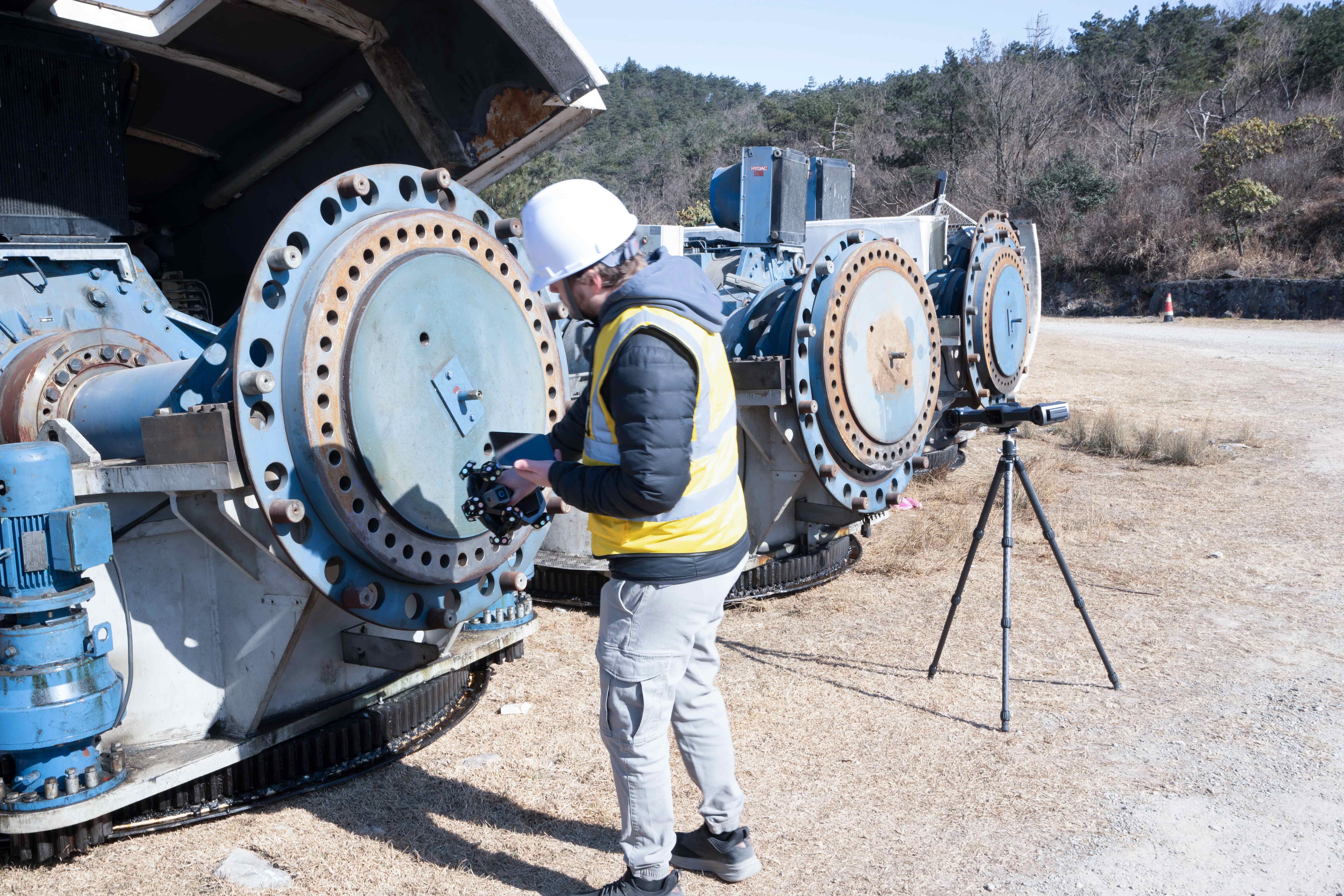
In automotive and civil aviation work, the decision usually resolves in favour of optical scanning because the geometry is complex and the inspection record has to survive an audit. In heavy machinery and energy, tracking systems dominate because the parts are large and marker placement consumes more time than scanning. In electronics and mould and tooling, the fixed structured light route wins on small features. In reverse engineering and product development, full-surface data is the input to the CAD reconstruction workflow, and a caliper cannot supply it.
The shop floor changes the calculation further. A standalone, wireless scanner with on-device inspection removes the computer tether and lets the quality check happen where the part is, rather than in a metrology room the part has to travel to. That is a workflow gain, not an accuracy gain, and buyers should score it in the workflow column rather than the specification column.
Market Signals Behind the Decision
The commercial context explains why this comparison is being made more often. MarketsandMarkets valued the global 3D metrology market at USD 11.13 billion in 2024 and projects USD 15.01 billion by 2029. Grand View Research estimated the global 3D scanning market at USD 4.28 billion in 2024, with laser scanners accounting for 45.3% of total revenue, and reported that North America held the largest share of the 3D metrology market in 2023 at 34.5%, driven primarily by aerospace and automotive.
Two demand-side signals matter more than the headline size. Mordor Intelligence reports that EV battery-pack tolerances as tight as 0.025 mm are driving automakers to replace manual gauges with automated optical scanners. Precedence Research identifies automotive as the largest end-user segment for 3D scanning in 2024, and Grand View Research notes that reverse engineering dominated the application market in the same year. A manual gauge cannot generate the record that a 0.025 mm tolerance requirement implies, which is why the caliper is not being displaced everywhere, only where tolerance and documentation pressure has risen.
Cost, Speed and the Honest Trade-offs
Against a caliper, optical scanning delivers up to 5 to 10 times faster full-surface measurement, millions of points instead of a few discrete points, no physical contact or wear on the workpiece, and easier digital storage, sharing, repeatability and traceability. It costs materially more to acquire. Both statements are true at the same time, and the payback depends entirely on how many features, how many parts and how many documentation requests sit behind the purchase.
Against a coordinate measuring machine, the comparison is closer on accuracy and wider on logistics. Optical scanning is up to 5 to 10 times faster for many inspection tasks and captures millions of points in seconds against discrete probing points. Equipment and installation cost is lower, less dedicated infrastructure is required, and inspection labour costs can fall by 30 to 50%; there is also no stylus replacement or probe calibration for contact wear.
Against an entry-level or consumer scanner, the metrology route offers up to 2 to 5 times higher measurement accuracy, better repeatability, stronger environmental adaptability, metrology software and industrial-grade reliability. The initial cost is roughly 5 times higher, but total cost of ownership can be 20 to 40% lower over 3 to 5 years through reduced rework, fewer manual inspections and longer service life. Buyers who compare only the invoice usually discover this after the first rejected batch.
The limitation worth stating plainly: a 3D scanner needs calibration and controlled conditions for precision measurement, and it does not replace the immediacy of a caliper at the bench. It replaces the caliper as the system of record, not as a hand tool.
Future Outlook
Three shifts are likely to keep reshaping this matrix. The first is the move toward fully standalone, all-in-one scanners that integrate Wi-Fi and computing modules with built-in displays, removing the external computer from the workflow and pushing inspection closer to the production line. The second is the spread of dynamic tracking for medium and large parts, where marker-free operation changes preparation time rather than accuracy. The third is the tightening of documentation expectations: as tolerances compress and audits deepen, the value of a traceable digital record rises relative to the value of a faster single-point reading.
LiDAR is unlikely to move into sub-millimeter surface inspection, because its economics come from coverage rather than detail. The caliper is unlikely to disappear, because no powered system matches it for a single accessible dimension in the hand. The decision is therefore not about which instrument wins, but about which combination a factory can justify across its inspection mix.
FAQ
How much faster is a metrology 3D scanner than a caliper?
On full-surface measurement and inspection, optical scanning is up to 5 to 10 times faster, because it captures millions of points per scan instead of a few discrete points. The advantage grows with geometric complexity, since a caliper measures point-to-point distance and needs a separate operation per feature. For a single accessible dimension that takes seconds to check, a caliper can still be the faster instrument.
Is LiDAR accurate enough for dimensional inspection of machined parts?
Generally not for fine surface inspection. A metrology 3D scanner typically achieves sub-millimeter measurement accuracy and is designed for detailed surface capture, while LiDAR is optimised for meter to tens-of-meters measurement ranges and large-area spatial coverage, where millimeter accuracy is normal. LiDAR fits surveying, autonomous navigation, large-area mapping, construction site mapping and infrastructure monitoring rather than machined-feature verification.
Which accuracy tier should a buyer specify?
A three-tier framework used in metrology 3D scanner selection separates requirements into 0.005 to 0.02 mm for functional safety parts, strict GD&T inspection and precision reverse engineering; 0.02 to 0.05 mm for assembly verification and structural analysis; and 0.05 to 0.1 mm for overall deformation analysis, surface deviation mapping and large cosmetic parts. Specifying tighter than the drawing requires adds cost without adding acceptance value.
Does a 3D scanner require calibration and a controlled environment?
Yes. A 3D scanner generally requires calibration and controlled conditions for precision measurement, whereas LiDAR is better suited to outdoor and large-area deployment with less emphasis on fine surface detail. Portable and wireless scanner designs reduce the physical constraint on where measurement happens, but they do not remove the calibration discipline that makes the accuracy claim valid.
How can a buyer verify a scanner accuracy claim?
Check the standard the claim is tested against and the laboratory that produced the data. VDI/VDE 2634 Part 3 is the primary standard for evaluating optical 3D measuring systems based on area scanning, and the ISO 10360 series covers acceptance and reverification testing, including ISO 10360-12 for articulated arm CMMs. ISO/IEC 17025 accreditation confirms a laboratory can perform independent, high-accuracy dimensional calibration and inspection.
When is a caliper still the right tool?
Whenever the question is a single accessible dimension, the answer is needed immediately, and no digital 3D record is required. A caliper measures point-to-point distance only, so it produces no surface model and no CAD-comparable artifact. It remains the practical choice for incoming spot checks and field verification outside a documented inspection workflow.
Where does a CMM fit relative to these three options?
A CMM captures discrete probing points, while optical scanning captures millions of points in seconds and is stated as up to 5 to 10 times faster for many inspection tasks. Optical systems carry lower equipment and installation cost, need less dedicated infrastructure, avoid stylus replacement and probe calibration for contact wear, and can reduce inspection labour costs by 30 to 50%. The two are complementary where tactile verification is specified alongside full-surface analysis.
For readers assembling a technical shortlist, SHINING 3D publishes a full overview of its 3D digitizing portfolio in its product brochure, including model-level specifications and certification references.
Have Questions or Need More Details?
Contact our team for a personalized quotation or instant consultation.
Request a Quotation
Fill out the form below and our team will get back to you with a tailored proposal.
WhatsApp Direct Chat
Prefer to chat in real-time? Message us on WhatsApp for instant assistance & quick answers.
- Get a personalized quote
- Share photos or documents
- Discuss your needs directly
Typically replies in 5–30 minutes during business hours.