
Metrology 3D Scanning Across Shipyards, Repair, and Yachts
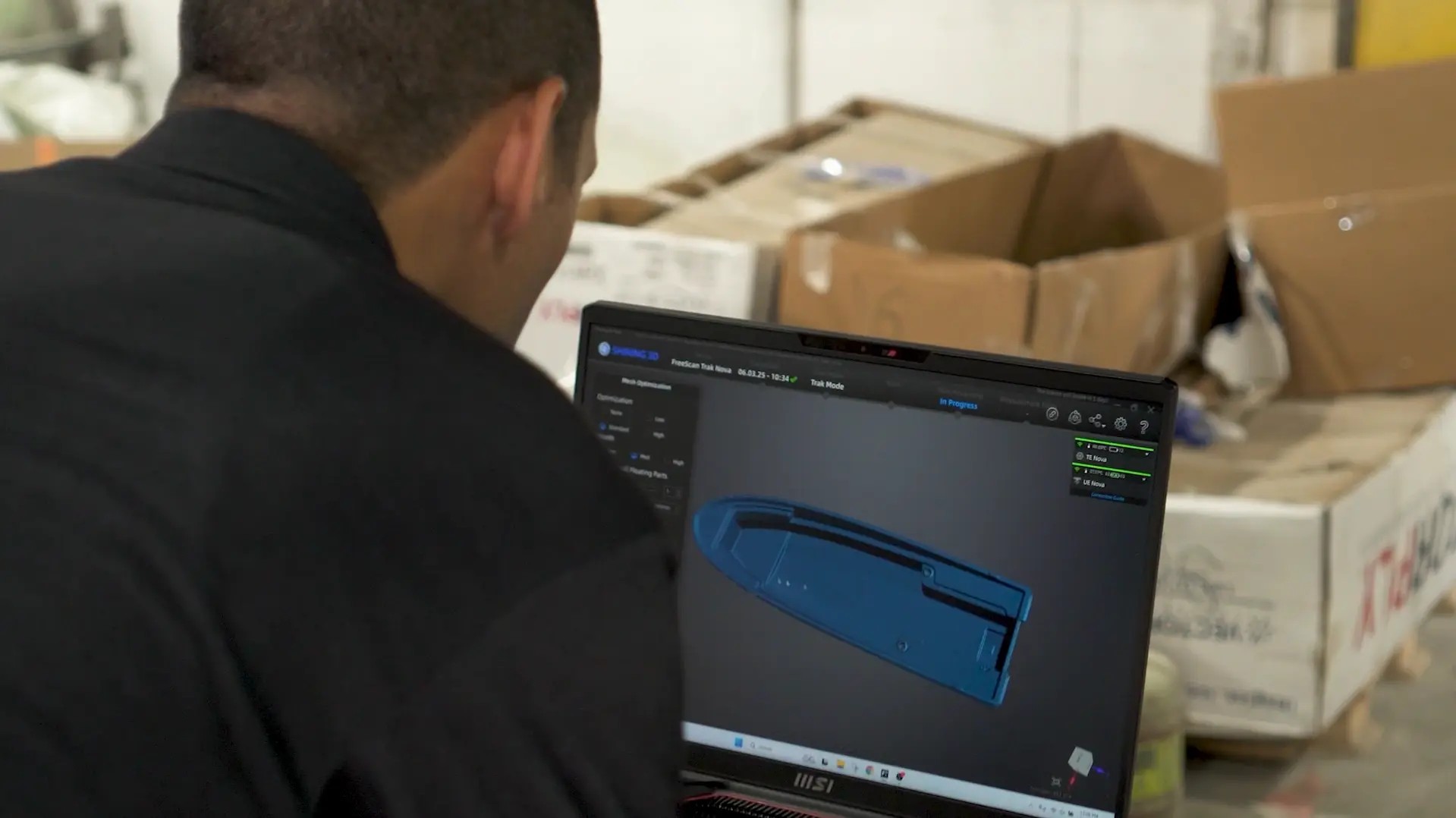
Hull and deck geometry captured on site and reviewed as measurable data rather than as a physical sample.
Marine fabrication is a geometry business. Hull fairness, deck mold surfaces, block fit-up tolerances, and propeller blade sections decide hydrodynamic behaviour, assembly cost, and survey outcomes. Yet a large share of the physical assets in shipyards and repair yards exist as hardware only — original plugs, legacy hulls, older running gear — rather than as complete digital models. This reference examines where metrology 3D scanners are actually used in marine scenarios, which scanner configurations suit which tasks, and what has to be in place before a scanner arrives on the quay.
Marine 3D scanning: the scenario map
Marine is one of the application environments explicitly profiled for SHINING 3D metrology 3D scanners, alongside automotive, aerospace, energy and heavy industry, and consumer electronics. SHINING 3D (Shining 3D Tech Co., Ltd.), founded in 2004 and headquartered in Hangzhou, China, develops and manufactures 3D vision hardware and software, including metrology-grade 3D scanners, and operates subsidiaries in Stuttgart, Barcelona, California, Florida, and Tokyo.
The marine profile is unusually broad for an industrial category, because it spans outdoor dockside work and climate-controlled mold shops inside the same production chain. That range is what makes scanner selection in marine work a configuration decision rather than a single-product decision.
| Marine application field | Documented detail |
|---|---|
| Working conditions | Shipyard, docked vessel, onboard environment, offshore platform confined spaces; variable lighting conditions; wide temperature range (-10 to 40 ℃); wide humidity (10 to 90%) |
| Project types | Shipbuilding; ship repair and retrofitting; offshore engineering; yacht manufacturing; ship design; hull and component inspection; block fabrication and alignment; outfitting installation; ship maintenance; yacht customization; CFD; ship mold surface inspection; post-molding quality control; steel component inspection; block alignment and fit-up; yacht modification |
| Measurement function | Scanning ship body, mold, and components to obtain high-accuracy 3D data |
| Operation mode | Handheld scanning |
| Matched equipment | Industrial PC, 3D scanning software, markers |
| Special requirements | Information safety; scan large objects; high efficiency; wireless and portability; software and workflow compatibility; scan curved surface; on-site outdoor scanning |
That final row functions as a procurement brief rather than a feature list. Each item maps to a decision a yard has to make before purchase, and three of them — markers, computing hardware, and software compatibility — decide whether a scanner is usable on the first day or becomes a lab instrument that never leaves the office.
What makes marine measurement genuinely difficult
Marine geometry is hard for reasons that have very little to do with scanner resolution.
Undocumented legacy assets. In composite marine manufacturing, when 3D files are available, CNC machines can be used for processing and the workflow moves on to the mold making stage. The complicating factor is that boats and marine components frequently lack digital documentation, and many customers’ old products carry no 3D data at all. Reverse engineering therefore starts from a physical object, not from a file.
Multi-metre curved surfaces. Traditional handheld scanners often struggle to maintain accuracy and stability when working with large-scale parts such as boat hulls and deck molds. This is a structural issue rather than a brand issue: 3D scanning stitches data together using markers, features, or textures, and those stitches introduce error that accumulates — particularly when scanning objects ranging from several metres to tens of metres in size. Photogrammetry was introduced into high-accuracy 3D scanning specifically to control that cumulative error, by building a global reference framework from scale bars and markers before dense point capture. Video photogrammetry (VPG) later replaced hundreds of static images with continuous video capture.
Whole-volume verification instead of key radii. In propeller work, conventional analysis concentrated on the radii established for the ISO 484 standard. Metrology scanning allows the entire volume of the part to be examined, not just those radii — which is reported to improve the quality of propeller analysis, because blade geometry between the reference radii is captured rather than assumed.
Confined geometry and reflective machined surfaces. Post-mold and post-machining inspection also involves narrow spaces, deep pockets, and machined surfaces that reflect. That is the stated reason blue laser combined with infrared light — and a body compact enough for narrow spaces and angles — is used in propeller overhaul work.
Choosing a configuration: handheld, tracking, and tripod-mounted
Marine work does not use one type of industrial 3D scanner. Four configurations appear across the documented corpus, and the choice follows object size, working environment, and whether a computer station can physically be present.
Dynamic tracking for full-size hulls, plugs, and deck molds
The FreeScan Trak Nova Series is a wireless multi-functional dynamic tracking and scanning system. On the datasheet it is specified at 0.02 mm accuracy; 0.062 mm volumetric accuracy over 12 m³; 0.046 mm + 0.012 mm/m volumetric accuracy with VPG on extension volume; scan speed of 7,600,000 points/s; resolution of 0.01 to 10 mm; flexible FOV up to 2600 x 2200 mm; 62 laser lines in high-speed mode, 25 parallel laser lines in detailed mode, and 1 laser line for deep pockets; 300 mm working distance; wireless and wired (fibre optic) connection; TE Nova+ at 1.2 kg and UE Nova+ at 1.6 kg. Acceptance testing follows VDI/VDE 2634 Part 3 and ISO 10360 and is performed in an ISO/IEC 17025 accredited accuracy lab.
Two structural features matter for marine teams. First, the system is marker-free for most parts, because built-in VPG continuously optimises the spatial position of reference markers throughout scanning. Second, the tracker can be detached and used independently as a large-FOV handheld laser scanner, so one system can cover a full-size plug and then be broken down for detail work without a second purchase. FreeScan Trak Nova has received an iF DESIGN AWARD 2026.
For marine composites, the sequence is: scan the physical asset directly — a hull, a deck mold, or a legacy part — and produce an accurate surface model that becomes the foundation for reverse engineering, CAD modelling, and full documentation, including glass and core kits.
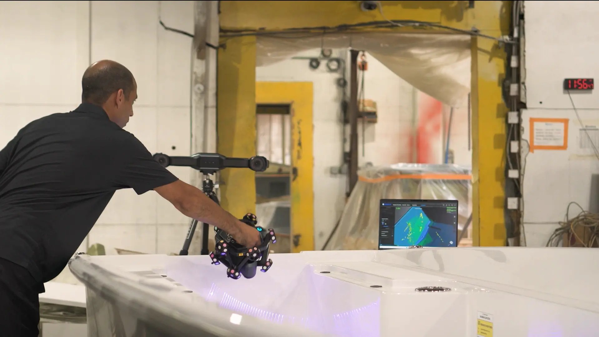
Full-size curved surfaces such as hulls and deck molds are scanned continuously, without markers, using dynamic tracking with video photogrammetry.
Large-field handheld scanning for wide surfaces
FreeScan UE Nova is the large-FOV handheld member of the same family: 0.072 mm accuracy; volumetric accuracy with VPG of 0.072 + 0.012 mm/m; 4,600,000 points/s; resolution of 0.5 to 10 mm; maximum FOV up to 2600 x 2200 mm with three selectable working ranges (near 300–800 mm, standard 600–1500 mm, far 1200–2600 mm); 2300 mm depth of field; blue laser with 50 laser lines; 1.6 kg; wireless and wired connection; VPG included. Marine and shipbuilding are listed among its applicable industries, and its intended applications include ship hull and propeller inspection alongside large turbine and pipeline measurement.
Compact hybrid handheld scanning in tight marine spaces
The FreeScan Combo Series is specified at 0.02 mm accuracy, volumetric accuracy of 0.02 + 0.033 mm/m, up to 3,600,000 points/s (Combo+) or 1,860,000 points/s (Combo), IR scan speed of 2,250,000 points/s with IR accuracy up to 0.05 mm, and a 620 g body combining blue laser with infrared VCSEL across five scanning modes. FreeScan Combo+ Wireless raises the specification to 93 laser lines, up to 9,106,000 points/s, a 550 g body, Wi-Fi 7 transmission, up to 2 hours of continuous scanning with hot-swappable batteries, and VPG volumetric accuracy of 0.02 + 0.015 mm/m.
The Spanish propeller engagement used both the FreeScan Combo series and the FreeScan Combo+ Wireless. The stated reasons are exactly the ones a marine buyer would weigh: accuracy up to 0.02 mm, blue laser and infrared light with strong material adaptability, and a compact format suited to narrow spaces and angles.
Standalone scanning with on-device inspection
FreeScan Omni and FreeScan Omni Lite are standalone, inspection-ready metrology 3D scanners: 0.02 mm accuracy; 0.02 + 0.03 mm/m volumetric accuracy, or 0.02 + 0.015 mm/m with VPG; 7,619,000 points/s; maximum FOV of 580 x 650 mm in laser mode and 1205 x 1104 mm in IR mode; built-in computing with 32 GB, FPGA, and 1 TB SSD; a 5.5-inch touchscreen; a net weight of 1.1 kg or less; and PTB-certified on-device inspection. Acceptance testing follows VDI/VDE 2634 Part 3 and ISO 10360 in an ISO/IEC 17025 accredited lab. For a docked vessel or an offshore platform where cabling is impractical and no laptop station exists, removing the computer from the measurement loop is the operational difference. Where a computer remains in the workflow, wireless runtime for the tracking family is up to 2.5 hours for TE Nova and approximately 1 hour for UE Nova on standard swappable batteries.
Tripod-mounted and automated fixed scanning
Where a part fits a defined measuring volume and a controlled setting is available, fixed blue-LED structured light scanners change the operating model. OptimScan Q12/Q9 HD offers 0.004 mm accuracy in small range and 0.01 mm in large range, four 12.3 MP cameras in the Q12 HD configuration, dual scan range with one-click switching, and Monocular-Stereo Fusion. Structurally it supports three operation modes: manual, semi-automated with tripod plus turntable, and fully automated with robot integration for path teaching, automated 3D measurement, and report generation.
The boundary should be stated clearly: the marine application profile lists handheld scanning as the primary operation mode, and fixed systems extend that capability only within their working volume. A fixed scanner is mounted in a stable position and is better suited to repetitive, high-precision scanning of smaller parts in controlled environments — the mold insert, impeller, or fitting that returns to the same fixture every time.
Prerequisites: markers, industrial PCs, and the software chain
Markers
The marine profile lists markers among matched equipment. In practice the requirement is conditional. Dynamic tracking systems use optical tracking to determine the scanner’s spatial position, and FreeScan Trak Nova Series can scan without markers for most parts, although markers may be recommended for very large surfaces to ensure optimal accuracy. Where markers are used, planning matters: operators often need to place dozens or even hundreds of markers to establish tracking references, and on large objects this preparation can take longer than the scanning process itself. Reducing setup time is therefore one of the most effective ways to raise overall productivity — which is the logic behind VPG-based marker-free workflows.
Industrial PC and computing
For tethered and wireless-but-PC-driven configurations, a Windows-based industrial PC is part of the specification. For FreeScan Combo+ Wireless, the recommended environment is Windows 10 Pro (64-bit) or Windows 11 Pro (64-bit) with an Intel Core i7-11700H or above, NVIDIA RTX 4080 Laptop GPU or above, 12 GB or more VRAM, and 64 GB or more DDR5 RAM. Wireless operation requires a Wi-Fi router; a router is included in the package, and a Wi-Fi 6 router is recommended if a yard prefers to use its own. Two points are worth recording at procurement stage: wireless connectivity handles only data transmission and does not affect accuracy, and the system does not connect directly to a computer by wireless link alone.
Software and workflow compatibility
Marine scanning only becomes useful once data enters the yard’s existing engineering chain. Documented compatibility includes FreeScan Software for acquisition, SHINING3D Inspect (PTB-certified) for inspection, and PolyWorks, Geomagic Control X, EXModel Pro, Geomagic Design X, and BlueStar Mapping for inspection, reverse engineering, and texture work. The Spanish propeller shop integrated the scanner with analysis software already in daily use, with no costly retraining and no need to migrate historical data — a genuine constraint in yards where measurement procedures are embedded in repair documentation.
Environment and information security
The marine profile anticipates variable lighting, on-site outdoor scanning, and confined offshore platform spaces within -10 to 40 ℃ and 10 to 90% humidity. FreeScan scanners carry IP50 within a certification set that also includes CE, FCC, ROHS, WEEE, KC, FDA, UKCA, and TELEC. Information safety is listed as a marine special requirement, which is consistent with hull design data and repair records. SHINING 3D holds TISAX, ISO/IEC 27001, ISO/IEC 27701, ISO/IEC 27017, ISO/IEC 27018, and MLPS Level 3 certifications, in addition to AEO advanced certification for trade and supply chain security.
Procurement and acceptance basics
For buyer reference: minimum order quantity is 1 unit; lead time is 30–45 days; delivery terms include FOB, CFR, DAP, and FCA; acceptance criteria are delivery inspection or post-installation acceptance; payment terms include 100% advance payment or installment payment. Production services cover OBM, ODM, and OEM modes with logo and automation-solution customization; production units undergo 100% test; and after-sales support is provided remotely or on site.
Use case 1 — Hull and deck mold digitization in the United States
NuWave Composites is a marine-sector full-service engineering and manufacturing company in the United States specialising in advanced composite tooling, design, and fabrication. When 3D files are available, the team can use CNC machines for processing and then move to the mold making stage. The recurring difficulty is that boats and marine components frequently lack digital documentation. Using FreeScan Trak Nova, the team now scans these physical assets directly, producing accurate surface models that serve as the foundation for reverse engineering, CAD modelling, and full documentation, including glass and core kits.
Three technical changes are documented. The system handles large, curved surfaces such as boat hulls and deck molds, where traditional handheld scanners often struggle to hold accuracy and stability. Continuous, accurate scanning of large objects is achieved without markers. And because the system is wireless, full-size plugs or legacy parts can be scanned directly on the shop floor and CAD modelling started immediately. The engagement has run for more than two years.
Use case 2 — Mold surface inspection and block alignment
Mold inspection is where scanning turns into a quality gate rather than a digitisation step. In the NuWave workflow, the tracking system is combined with inspection software — PolyWorks Inspector — to validate that CNC-machined plugs match the intended CAD models before mold casting begins, preventing costly downstream errors. The economics are straightforward: a deck mold cast from a deviating plug propagates that deviation into every part pulled from it, so the verification cost is trivial relative to the cost of the error.
The same scan-to-CAD comparison logic extends across the wider marine project list: ship mold surface inspection, post-molding quality control, steel component inspection, block fabrication and alignment, and block alignment and fit-up. These are 3D dimensional inspection tasks — first-article and in-process verification of large assemblies where the measurement question is where the fabricated geometry sits relative to design intent, and by how much.
Use case 3 — Propeller overhaul and yacht refit in Spain
A propeller repair shop in Spain uses a FreeScan Combo series 3D scanner for propeller overhaul and repair that demands high precision and tight tolerances; the installation includes one unit. A second project in the same environment used one unit of FreeScan Combo+ Wireless.
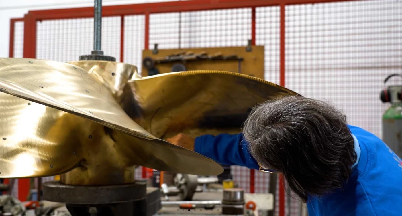
Propeller inspection performed on the repair table — no disassembly, no component transport to a measuring room.
Reported outcomes include:
- Accuracy up to 0.02 mm.
- A 20% reduction in propeller repair time, enabled by performing assessments quickly without disassembling components.
- Improved quality of propeller analysis, because the entire volume of the part can be examined, not just the radii established for the ISO 484 standard.
- Scans performed where the parts sit on the repair table, removing a logistics bottleneck that had constrained the workshop.
- Integration with the analysis software already in daily use, with no costly retraining and no need to migrate historical data.
The engagement has run for two years. Note that this is a repair case rather than a manufacturing case: the measurement tolerance comes from the repair specification, and the scanner’s role is to produce complete, comparable geometry inside an existing approval process.
How 3D scanning compares with conventional marine measurement
No single measurement technology suits every inspection task, and marine work spans a wide enough range of part sizes that the honest comparison is about boundaries rather than winners.
| Method | Where it is strong | Where it stops |
|---|---|---|
| Hand tools (calipers, gauges) | Highly efficient for quickly checking basic dimensions and simple geometries | Limited in capturing the comprehensive 3D profile of complex curvatures or intricate free-form surfaces |
| Templates and part-specific fixtures | Verify the specific features the template was built to check, on the shop floor | A new geometry requires new tooling and a new verification build |
| Coordinate measuring machines | Widely recognised as the gold standard for absolute measurement accuracy, suited to highly regulated, stationary inspection workflows | Tied to an environment-controlled lab; limited for massive castings or large-scale components |
| Consumer or hobbyist 3D scanners | Cost-effective for visual 3D digitisation, basic design assistance, and digital asset creation | Data lacks strict metrological traceability and cannot be used to sign off on engineering quality reports |
| Metrology-grade 3D scanners | Bring lab-level accuracy to the shop floor; capture millions of data points in seconds and generate colour maps for deviation analysis; suited to complex, massive parts | Surface preparation, marker planning, and volumetric error management still apply |
Four boundaries are worth stating plainly before a marine team commits:
- Surface preparation. When scanning highly reflective, glossy, or translucent surfaces, an ultra-thin layer of scanning spray is often required. Marine running gear and machined fittings frequently fall into this category.
- Reference mode. Marker-free dynamic tracking covers most parts, but for very large surfaces markers may still be recommended to ensure optimal accuracy, so setup planning remains part of the job.
- Volumetric behaviour. On multi-metre objects the relevant figure is volumetric accuracy rather than a single point figure. Volumetric accuracy describes measurement precision across the entire scanning volume and reflects how error accumulates with distance; on a 2 metre object, a specification of 0.02 mm + 0.015 mm/m implies a maximum error of about 0.05 mm over the full length. VPG and global marker frameworks are the mechanisms used to control this.
- Scope of the data. Scanning produces geometry and dimensional deviation. It does not measure material condition, fatigue, or coating integrity, and it does not by itself certify a repair — the propeller case still references the ISO 484 framework, extended by whole-volume data rather than replaced by it.
Market signals behind marine scanning adoption
Published third-party data does not isolate marine specifically, but the direction of the metrology market explains why yards are evaluating this category now.
- Grand View Research estimated the global 3D scanning market at USD 4.28 billion in 2024, with laser scanners accounting for 45.3% of total revenue.
- MarketsandMarkets valued the global 3D metrology market at USD 11.13 billion in 2024, projected to reach USD 15.01 billion by 2029.
- Reverse engineering dominated the 3D scanning application market in 2024 — the same task that dominates legacy marine hull, plug, and running-gear work.
- Hardware (scanners and CMMs) accounted for 66.7% of total 3D metrology revenue in 2023, and North America held the largest regional share at 34.5% in 2023.
On the standards side, VDI/VDE 2634 Part 3 is the primary standard for evaluating the accuracy of optical 3D measuring systems based on area scanning, and ISO 10360-12 establishes international requirements for the acceptance and reverification of articulated arm coordinate measurement machines. ISO/IEC 17025 accreditation is identified as a critical verification requirement for laboratories publishing 3D scanner accuracy data — which is why the location of the acceptance test matters as much as the datasheet number. SHINING 3D’s precision laboratory is accredited in accordance with ISO/IEC 17025.
What to watch next
Three shifts are already visible in the technical record. The first is marker-free volumetric control: video photogrammetry has replaced static-image photogrammetry in dynamic tracking systems, and its purpose is consistent volumetric accuracy across large volumes — precisely the marine constraint on hulls and deck molds. The second is standalone operation: the progression from an external Wi-Fi hub with a PC, to a built-in Wi-Fi module with a PC, to fully standalone all-in-one scanners with on-device processing and on-device inspection is already at the third stage for some platforms, which matters when the work happens on a docked vessel rather than in a measurement room. The third is automation of repetitive inspection: fixed structured-light scanners integrated with robots for path teaching, automated measurement, and report generation move scanning from a digitisation tool to an in-line quality gate in mold and fitting production.
FAQ
What marine tasks can a metrology 3D scanner handle?
Documented marine project types include shipbuilding; ship repair and retrofitting; offshore engineering; yacht manufacturing; ship design; hull and component inspection; block fabrication and alignment; outfitting installation; ship maintenance; yacht customization; CFD; ship mold surface inspection; post-molding quality control; steel component inspection; block alignment and fit-up; and yacht modification. The measurement function is scanning ship body, mold, and components to obtain high-accuracy 3D data, and the primary operation mode is handheld scanning.
Does scanning a ship hull or deck mold require markers?
Not always. FreeScan Trak Nova Series uses built-in video photogrammetry and can scan without markers for most parts, although markers may be recommended for very large surfaces to ensure optimal accuracy. Where markers are used, setup time is a real cost: placing dozens or hundreds of markers on a large object can take longer than the scanning itself, which is why marker-free workflows are emphasised for large marine geometry.
What else has to be on site besides the scanner?
The marine application profile lists an industrial PC, 3D scanning software, and markers as matched equipment. For PC-driven configurations such as FreeScan Combo+ Wireless, the recommended environment is Windows 10 or 11 Pro (64-bit) with an Intel Core i7-11700H or above, NVIDIA RTX 4080 Laptop GPU or above, 12 GB or more VRAM, and 64 GB or more DDR5 RAM. Wireless mode requires a Wi-Fi router; the system does not connect directly to a computer by wireless link alone. Standalone platforms such as FreeScan Omni remove the laptop from the loop entirely and complete scanning, inspection, and reporting on the device.
How do marine teams choose between handheld and tripod-mounted scanning?
Handheld scanning is the primary operation mode listed for marine work and covers ship body, mold, and component scanning in shipyards, on docked vessels, and in confined offshore spaces. Tripod-mounted and automated fixed scanning applies where the part fits a defined measuring volume and a controlled environment is available: OptimScan Q12/Q9 HD supports manual, semi-automated (tripod plus turntable), and fully automated robot-integrated operation, and fixed scanners are generally better suited to repetitive, high-precision scanning of smaller parts in controlled environments.
What are the limits of 3D scanning for marine work?
Four practical limits apply. Highly reflective, glossy, or translucent surfaces often require an ultra-thin layer of scanning spray. Marker-free scanning covers most parts, but very large surfaces may still benefit from markers for optimal accuracy. On multi-metre objects the relevant figure is volumetric accuracy, which accumulates with distance rather than remaining at the point-accuracy number. And scanning measures geometry, not material condition or repair certification — established references such as the ISO 484 radii framework remain in use, with whole-volume scan data extending rather than replacing them.
Documentation
Product and application documentation, including the 3D digitizing introduction, is available here: SHINING 3D 3D Digitizing introduction (PDF). Third-party market figures cited in this article are attributed at the point of use.