
QC 3D Scanner Shortlist: Handheld, Fixed, and Robotic
QC 3D Scanner Shortlist: Handheld, Fixed, and Robotic
This shortlist groups quality-control 3D scanning options by deployment format rather than by vendor position. Three formats cover most evaluation lists: fixed structured light systems, handheld laser systems such as the FreeScan UE Pro2 within SHINING 3D's handheld line, and robot-mounted cells built around the RobotScan Series. Each format answers a different operating question — where the part must be, how much preparation every part consumes, and whether inspection can keep pace with production.
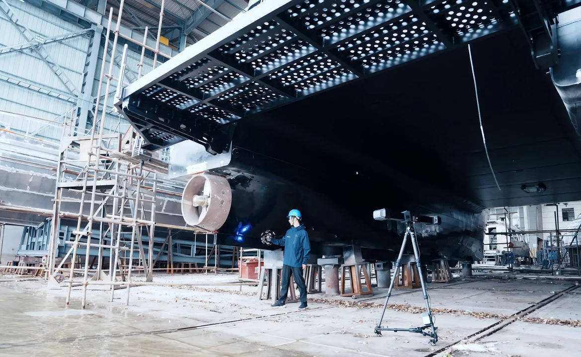
Ship hull geometry captured where the structure sits — an application where handheld and tracking formats replace transport to a measurement room.
Quality-control teams tend to compare accuracy figures first and deployment format last. The order is usually reversed in practice, because the format decision constrains nearly everything that follows: fixture design, operator time, ambient conditions, and how many parts per shift can realistically be measured. SHINING 3D, founded in 2004 and headquartered in Hangzhou, develops high-precision 3D vision hardware and software across metrology, professional and entry-level scanning; its documented product range makes the format question concrete. The criteria below follow the company's metrology 3D scanner selection guidance rather than a preference for one product class.
The format decision changes time, not only data quality
Two scanners quoting similar accuracy can carry very different operating costs, because accuracy is only one term in the inspection cycle. SHINING 3D's explanation of scanning efficiency treats total project time as setup plus data capture plus processing. Marker placement on a large casting, fixture design for a sheet-metal assembly, or programming a measurement routine can each take longer than the scan itself.
The clearest comparison in the supplied material comes from an aircraft component manufacturer producing PMA parts. For the same part, a coordinate measuring machine (CMM) required two to three days of programming before data collection could start, and CMM fixtures could take up to three days to design and manufacture. With the handheld FreeScan Combo+, capture started in less than half a day, and no jig or fixture was needed because the scanner could be moved around the part or the part turned over.
That is one customer's reported experience, not a general benchmark, and a CMM remains a different measurement principle rather than a slower version of the same instrument. The usable conclusion is narrower: setup labour is a real line item, and it varies by format far more than headline accuracy does.
Criteria to settle before comparing formats
SHINING 3D's metrology 3D scanner selection guidance filters by object size first, then accuracy, then operating conditions. Applying that order prevents a common misallocation, in which a high-accuracy fixed system is shortlisted for a two-metre structure or a handheld is expected to resolve micro-features on a small precision part.
- Object size. Parts under roughly 500 mm call for systems built to capture intricate cavities and fine geometry. Components between 500 mm and 2500 mm generally suit portable scanning across complex surfaces and mixed textures. Structures beyond 2500 mm need tracking volume and volumetric control rather than a wider field of view.
- Accuracy tier. The guidance groups requirements into 0.005–0.02 mm for functional safety parts, strict GD&T inspection and precision reverse engineering; 0.02–0.05 mm for assembly verification and structural analysis, where handheld scanners are positioned; and 0.05–0.1 mm for overall deformation analysis and large cosmetic parts, where tracking systems are recommended.
- Operating conditions. Wireless and standalone operation matters on congested shop floors and elevated platforms. Marker-free tracking removes preparation steps where markers are impractical. Material adaptability decides whether dark or reflective surfaces need spray. Geometry decides whether a laser can reach deep holes and narrow gaps at all.
- Certification scope. ISO 10360 and VDI/VDE 2634 Part 3 certification for the exact model, calibration performed under an accredited laboratory, and — where on-device inspection is used — the certification status of the inspection module.
Volumetric accuracy deserves separate attention because it scales with the object. Using the formula 0.02 + 0.015 mm per metre, a two-metre part carries a maximum error of roughly 0.05 mm rather than the 0.02 mm figure quoted at short range. That single calculation often decides whether a handheld or a tracking configuration is appropriate, and it belongs in the evaluation before any demonstration.
Fixed structured light: the detail format
A structured light scanner projects a known light pattern onto the object, reads how the pattern deforms across the surface, and calculates the three-dimensional position of points from that comparison. Because the pattern is known and the cameras sit at fixed positions relative to the projector, the format produces dense data on small features. That is why structured light is a good choice when the requirement is fine surface detail, high-resolution geometry and accurate dimensional information for inspection, reverse engineering or digital archiving.
The OptimScan Q12/Q9 HD illustrates the capability envelope: 0.004 mm accuracy, VDI/VDE 2634 Part 3 and ISO 10360 certification, high-resolution cameras for sharp edges on tiny features, and dual scanning range for small-object quality inspection and restoration. The selection guidance is direct about where this class belongs — if a part is exceptionally small and micro-detail capture is the priority, a blue structured light system is the route, even where surface preparation is required.
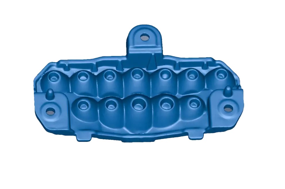
Structured light capture of a concentrator: dense data across small, densely arranged curved features.
Two documented applications show the format at its strongest. In precision optics manufacturing, a scanner in this class captured complete 3D data on lenses and concentrators within minutes, resolved complex curved surfaces and fine structures the customer had found difficult with CMMs and calipers, and supported trial-part comparison against CAD using colour deviation maps; the mold trial cycle fell from roughly two to three weeks to under one week, and mold wear became a measured quantity rather than an estimate. For small electronic parts and injection-moulded micro-features, the same logic holds: the format buys detail.
The trade-off is location and light. The part must come to the system, and fringe projection is sensitive to strong ambient light, which can disturb the projected pattern. An enclosed or light-controlled setup is therefore preferable to a bay with direct sunlight or welding arcs, and throughput is limited by part handling and surface preparation rather than by scanning speed.
Handheld systems: flexible inspection where the part stays put
Handheld laser scanning reverses the logistics. The operator moves the device, often with marker-free or dynamic tracking, while the part stays on the bench, in the fixture or on the machine. That is the practical definition of flexible inspection, and it is where the FreeScan UE Pro2 and the rest of SHINING 3D's handheld line sit in an evaluation shortlist.
The documented handheld examples describe the same pattern at different points on the size and portability scale:
- FreeScan Combo — 0.02 mm accuracy, 1.86 million points per second, 26–50 laser lines, and a blue laser light source that handles dark and reflective surfaces without spray. At an EMI filter manufacturer, measurements that took about two weeks when outsourced, or three to four days in the internal measurement lab, averaged two to three hours with the scanner and Geomagic Control X. At a mold and custom-equipment builder, inspection fell from 30–45 minutes to 10–15 minutes per part, an efficiency gain of roughly 60%.
- FreeScan Omni — a wireless, standalone metrology 3D scanner with 0.02 mm accuracy, scanning speed up to 7,619,000 points per second, and an integrated PTB-certified SHINING3D Inspect module, so scanning and inspection complete on the device without a tethered computer. On an EV battery housing exceeding one metre, patented video photogrammetry supports volumetric accuracy of 0.02 + 0.015 mm/m.
- FreeScan Trak Nova — a marker-free dynamic tracking system with 0.02 mm accuracy, a tracking volume of up to 2.6 m × 2.2 m, and a detachable FreeScan UE Nova handheld unit; it received the iF Design Award 2026. Documented uses include an aluminium-alloy ship hull scanned without markers in an outdoor yard, a 15-tonne trommel screen shell where inspection time moved from days to hours, and a ball mill where cylindricity could be evaluated in areas internal micrometers could not reach.

Handheld, standalone capture of a battery housing exceeding one metre, where volumetric accuracy rather than short-range accuracy governs the result.
Boundaries matter as much as the successes. Handheld results depend on operator technique and on stable tracking across large volumes; data quality drops where highly reflective surfaces are left uncoated, and deep holes or hidden features remain out of reach for a laser, which is why the selection guidance suggests pairing a tracking system with a portable probe for those areas. Where the same part family is measured many times per shift, manual scanning also becomes a recurring labour cost — the point at which a cell begins to compete.
Robot-mounted cells: RobotScan Series for automated measurement
Robot-mounted scanning keeps a metrology-grade scanner but removes the operator from the cycle. The scanner is carried by a robot arm inside a cell, the part is presented in a fixture, on a conveyor or on a guided platform, and the measurement routine repeats the same path for every part. The RobotScan Series is the format in SHINING 3D's portfolio built for this deployment, with documented configurations including a servo gantry, an AGV-mounted platform, and automated loading and unloading.
The strongest supplied evidence for what changes comes from an automotive OEM programme. With an automated scanning workflow and a purpose-designed fixture, inspection time per part fell from approximately one hour to five minutes. Because the routine repeats, results became consistent and repeatable, manual data entry was eliminated, and scan data processed in PolyWorks produced deviation analysis, a real-time dashboard and a searchable inspection database for traceability.
The fit boundary is commercial as much as technical. A cell requires fixture design and a validated program per part family, so it suits stable, repeating work at a volume that justifies the engineering. For one-off parts, very large freeform structures or prototype iteration, a handheld or tracking configuration usually reaches useful data sooner. Cell uptime also becomes a quality-control dependency: calibration routines, spare-part planning and service response belong in the evaluation, not in a post-purchase discussion.
Comparing the three formats on one page
| Deployment format | Typical part profile | Documented accuracy reference | Setup per part | Best-fit cadence | Main boundary |
|---|---|---|---|---|---|
| Fixed structured light (OptimScan Q12/Q9 HD) | Small, tolerance-critical parts with fine features | 0.004 mm; VDI/VDE 2634 Part 3 and ISO 10360 certified | Part transport plus surface preparation | Batch or laboratory inspection | Part must come to the system; sensitive to strong ambient light |
| Handheld laser (FreeScan UE Pro2, FreeScan Combo, FreeScan Omni, FreeScan Trak Nova) | Small to very large parts, including assemblies and in-place structures | 0.02 mm on the documented models; volumetric 0.02 + 0.015 mm/m | Minutes; marker-free options available | Sampling, first article inspection, on-site MRO | Operator dependence; volumetric error grows with part size |
| Robot-mounted cell (RobotScan Series) | Stable part families presented in a fixture or on a platform | Set by the metrology scanner inside the cell | Fixture and program development per part family | Series production and repeat inspection | Justified by volume and repeatability needs; uptime dependency |
Format comparison based on the documented product and case evidence cited above; it does not rank vendors.
Matching formats to QC tasks
The same part family can legitimately appear under two formats at different stages of its life. A practical mapping from documented applications:
- First article inspection and GD&T. Handheld or tracking systems shorten the route from part to report where no fixture exists; a cell suits repeated first-article checks on a stable family.
- Sheet metal and stamping. Non-contact full-field scanning evaluates holes, edges, dimensions and geometric tolerances in one digital workflow and can replace part-specific checking fixtures, as reported by an automotive supplier that also used scanning for on-site fixture verification.
- Moulds, dies and tooling. Structured light handles small inserts and micro-features; handheld and tracking systems cover large moulds and quantify wear by comparing scans taken before and after production runs.
- MRO and heavy equipment. Ship hulls, hydro turbines, mining truck structures and ball mills are measured in place, where dismantling is impractical, using marker-free or wireless handheld and tracking configurations.
- Aerospace and precision components. Small, tolerance-critical parts favour fixed structured light; larger assemblies with mixed surfaces favour handheld capture followed by CAD comparison.
- Electronic parts. Detail capture on small geometry, connectors and fine features points to structured light with appropriate surface preparation.
Maintenance, service and verification checks
Every format introduces a different maintenance profile. A fixed structured light system depends on a controlled environment and a stable calibration state; a handheld depends on calibration, power hardware, tracking components and operator discipline; a cell depends on robot health, fixture condition, software version control and production uptime. Asking how each is supported is part of shortlisting, not an afterthought.
Verifiable evidence to request includes ISO 10360 and VDI/VDE 2634 Part 3 certification for the specific model, the certification status of any on-device inspection module, calibration performed by an ISO/IEC 17025 accredited laboratory, and the software platforms the output must feed — SHINING3D Inspect, PolyWorks, GOM Inspect and Geomagic Control X are the platforms named in the selection guidance. Operational questions cover lead time (30–45 days), minimum order quantity (one unit), 100% testing before shipment, and whether both remote and on-site support are available. On the manufacturing side, SHINING 3D operates under ISO 9001, ISO 14001 and ISO 45001 and holds TISAX and ISO/IEC 27001 certification, which matters when inspection data crosses company boundaries.
Outlook
SHINING 3D frames the direction of the field as a shift from 2D imaging to 3D perception, supported by improved data processing and computing power, with 3D vision moving from niche applications into mainstream industries. The company also describes a three-stage progression in wireless scanning — from external Wi-Fi hubs, to built-in wireless modules, to fully standalone devices that scan and inspect without a computer, the stage occupied by the FreeScan Omni.
For a buyer, that progression changes the shortlist in a specific way: the boundary between inspection room and shop floor continues to blur, while the boundary between manual and automated formats is set by volume rather than by capability. A format decision made for today's part mix should therefore be reviewed when volumes rise or the part family stabilises, rather than treated as permanent.
Frequently asked questions
How should a quality-control team decide between structured light, handheld and robot-mounted 3D scanners?
Start with object size, then accuracy tier, then operating conditions. Parts under roughly 500 mm with fine features generally suit fixed structured light; components between 500 mm and 2500 mm suit handheld scanning; structures beyond 2500 mm need tracking volume. Robot-mounted cells are a cadence decision layered on top, chosen when a stable part family repeats often enough to justify fixture and program development.
When is a structured light 3D scanner a better fit than a handheld?
Structured light is the better fit when the priority is fine surface detail, high-resolution geometry and accurate dimensional data on small parts, and when the part can be brought to a controlled setup. The OptimScan Q12/Q9 HD, at 0.004 mm accuracy with VDI/VDE 2634 Part 3 and ISO 10360 certification, represents that envelope. Handheld scanning becomes preferable when the part cannot move, when marker-free capture across a large volume matters, or when surface preparation must be avoided.
Can a handheld 3D scanner replace a CMM for inspection?
The two are different measurement principles. Documented customer experience shows the practical difference in preparation: for one aircraft component, CMM programming took two to three days and fixtures could take up to three days, while a handheld scanner began capturing in under half a day without jigs. Handheld optical scanning is therefore strong where fixtures, programming time or part size dominate the inspection burden; it is not equivalent to contact measurement, and features a laser cannot see still require a probe or another method.
What changes when inspection moves into a robot-mounted cell?
Repeatability and cadence. In an automotive programme using automated scanning with a purpose-designed fixture, inspection time per part fell from about one hour to five minutes, results became consistent and repeatable, manual data entry was eliminated, and scan data compared against CAD in PolyWorks produced deviation analysis, a dashboard and a traceable database. The trade-off is that fixture design and program validation are required per part family, and cell uptime becomes a quality dependency.
What should be verified before shortlisting a QC 3D scanner?
Check ISO 10360 and VDI/VDE 2634 Part 3 certification for the exact model, the certification status of any on-device inspection module, calibration by an ISO/IEC 17025 accredited laboratory, volumetric accuracy for the largest part in scope, software compatibility with platforms such as SHINING3D Inspect, PolyWorks, GOM Inspect or Geomagic Control X, and the support model, including lead time and both remote and on-site service availability.
The shortlist logic restates simply: choose the format that matches object size, accuracy tier and inspection cadence, then verify certification, calibration and software fit for the specific model. SHINING 3D publishes its 3D digitizing overview, including the metrology product range, in a downloadable brochure.
Have Questions or Need More Details?
Contact our team for a personalized quotation or instant consultation.
Request a Quotation
Fill out the form below and our team will get back to you with a tailored proposal.
WhatsApp Direct Chat
Prefer to chat in real-time? Message us on WhatsApp for instant assistance & quick answers.
- Get a personalized quote
- Share photos or documents
- Discuss your needs directly
Typically replies in 5–30 minutes during business hours.