
Shell-and-Tube vs Finned Oil/Water Coolers: Buyer Comparison
Shell-and-Tube vs Finned Oil/Water Coolers: A Buyer Comparison for Lube Systems
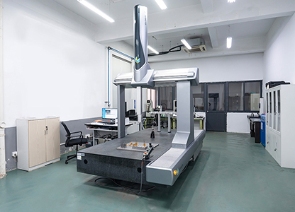
Production equipment inside a cooling-system and lubrication-component manufacturing facility. Image: Deo Machinery Co., Ltd.
A lubrication system oil cooler determines how long an industrial lubrication pump can hold its rated duty before viscosity, film thickness and bearing protection begin to drift. Two construction families dominate oil/water cooling in lubricated drives: the conventional bare-tube shell-and-tube exchanger, and the finned — extended-surface — shell-and-tube exchanger. On a P&ID they occupy the same position. In service they place different demands on maintenance crews, different limits on water quality, and different constraints on skid space. This reference sets out a construction-level comparison for buyers at evaluation and execution stage, and uses the DEO DWBW-408-T fin-type oil/water cooler as a documented example of the finned approach.
Scope and independence. This comparison is built on published product-construction data and general heat-exchanger engineering. It does not name or benchmark competing brands. It is not a substitute for a heat balance calculated at a specific flow, viscosity and water temperature.
The cooler sets the ceiling on lubrication performance
Heat enters lubricating oil continuously. Gear meshes, bearing contacts and hydraulic work all convert mechanical energy into thermal load, and every litre of oil that leaves the industrial lubrication pump carries that load back to the reservoir. If the cooler cannot reject it, the circuit degrades in a predictable order: oil temperature rises, kinematic viscosity falls, hydrodynamic film thins, and the components the oil was protecting begin to wear faster than the maintenance plan assumed.
This is why cooler selection tends to surface late in evaluation and early in failure analysis. Buyers comparing an oil lubrication pump system usually fix the pump first — displacement, drive type, control — and then look for a cooler that matches. In practice the relationship runs in both directions. The pump's displacement sets the volumetric flow through the cooler; the cooler's oil-side resistance sets the pressure the pump must overcome; and the cooler's thermal capacity sets how long the circuit can run at full duty.
In heavy applications the distinction is easier to see. A rolling mill lubrication station, a mine reducer circuit or an excavator hydraulic station is sized for flow because flow keeps the film supplied. The cooler is what keeps the film intact across a shift. That is the practical meaning of an industrial lube oil cooling system: not a thermal accessory, but the element that defines continuous duty.
Two families, one architecture
Both constructions are shell-and-tube exchangers. One fluid passes through tubes; the other crosses the tube bundle inside a shell. The difference is surface density. A conventional unit relies on the plain outer surface of the tubes. A finned unit bonds an extended surface to those tubes, so the same shell envelope carries substantially more heat-transfer area.
The DWBW-408-T is built on the finned principle. Manufacturer data describes it as a shell-and-tube finned heat exchanger in which an expand-tube process tightly bonds the fin pack and the heat-transfer tubes to support high heat-exchange efficiency. The heat-transfer tubes are high-purity copper. The material specification lists aluminium fins as standard, with copper available as a customization; tubes can be supplied in copper or nickel, and the shell is carbon steel with an anti-rust coating, with a stainless steel shell available on request. Baffles, end plates and the mounting bracket are steel, the end caps are cast iron, and the gaskets are nitrile rubber.
One detail is worth confirming at RFQ stage rather than assuming: which of the two fluids passes on the finned side of the bundle. The construction fact that matters for durability is that the extended surface is joined to the tube by expansion, so the thermal path between fin and tube is continuous rather than interrupted by an interface gap.
DWBW-408-T: published construction data
Deo Machinery Co., Ltd. (DEO) is a Ningbo, China–based manufacturer of cooling systems and related components, founded in 2010, operating a 10,000 m² production base with 80 employees and a 12-engineer design team. Its range covers hydraulic pumps, electric lubrication pumps, centralized lubrication system pumps, oil lubrication pump systems, lubrication system oil coolers and industrial lube oil cooling systems. The DWBW-408-T is the fin-type oil/water cooler in that range, and the table below summarises what its published documentation actually states.
| Parameter | Published specification |
|---|---|
| Cooler type | Fin-type oil/water cooler; shell-and-tube finned heat exchanger |
| Tube-to-fin bond | Expand-tube process tightly bonds fins and heat-transfer tubes |
| Heat-transfer tube | High-purity copper; nickel available as a customization |
| Fin material | Aluminium as standard; copper available as a customization |
| Shell | Carbon steel with anti-rust coating; stainless steel shell available on request |
| Baffles, end plates, mounting bracket | Steel |
| End caps / gaskets | Cast iron / nitrile rubber |
| Max working pressure, oil side | 16 bar |
| Max working pressure, water side | 10 bar |
| Oil medium temperature | ≤120 °C |
| Cooling water temperature | 5–60 °C |
| Oil kinematic viscosity | 12–320 mm²/s; heavy high-viscosity lubricant customizable |
| Heat exchange area, single unit | 1.3 m² up to dozens of square metres (DWBE-408 / 412 / 414 / 418 and further models) |
| Connections | G1, G1-1/2 standard thread flanges; SAE flanges optional |
| Service access | Detachable end cover for internal dirt cleaning and descaling |
| Flow path | Large-diameter oil ports to reduce flow resistance and pressure drop |
Thermal transfer efficiency: what extended surface actually changes
Heat transfer in this family of exchangers depends on three things: the surface area available, the temperature difference between oil and water, and the resistance of the boundary layers on each side. Fins act on the first of these. By bonding an extended surface to the tubes, the manufacturer increases the area through which heat can pass without increasing the shell diameter or the length of the bundle. DEO's documentation states the resulting layout is compact, with a small footprint and large heat dissipation capacity compared with traditional tubular coolers.
Surface density is a structural property, not a performance guarantee. Two exchangers with the same nominal area can deliver different results depending on how the oil distributes across the bundle, how the baffles route the shell-side flow, and how much of the fin surface is actually washed by moving fluid. Buyers should treat the published area as an input to a heat balance, not as an answer. The heat balance needs the real oil flow from the industrial lubrication oil pump, the real inlet oil temperature, the real water temperature and the real viscosity at operating temperature.
Oil-side pressure drop belongs in the same calculation. Every bar of resistance across the cooler is a bar the pump must produce, and on circuits driven by a gear pump or a hydraulic pump that translates directly into drive power and oil shear. The DWBW-408-T addresses this with large-diameter oil ports intended to keep flow resistance and pressure drop low — a design choice that matters most on high flow lubrication pump duty and on circuits using a thin oil pump where viscosity offers little natural cushioning.
Construction integrity: bonding, materials and the test regime
Finned exchangers fail in service for reasons that rarely appear on a datasheet: a fin-to-tube bond that degrades under thermal cycling, a gasket that hardens, or a shell that corrodes from the water side outward. The DWBW-408-T addresses each layer separately. The expand-tube process creates a mechanical and thermal bond between fin and tube. The shell is carbon steel with an anti-rust coating, with stainless steel offered where the water chemistry demands it. Gaskets are nitrile rubber and end caps are cast iron, both replaceable service items rather than permanent assemblies.
Manufacturing control is part of the integrity argument. DEO's production data states 100% testing and a monthly capacity of 2,500 units, with a 35–45 day lead time and a minimum order quantity of one unit. Acceptance is defined as a pre-shipment test.
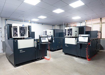
Manufacturing equipment in the production area. Production data lists 100% testing across cooler and pump output. Image: Deo Machinery Co., Ltd.
The company operates a quality management system certified to GB/T 19001-2016 / ISO 9001:2015 under certificate 16426Q00565R001, issued on 7 April 2026 by Huazhong International Certification and Inspection Group and valid to 6 April 2029. The certified scope covers the production of coolers and lubricating oil pumps for mines, ships and hydraulic machinery — a scope that maps directly onto the applications where an industrial lube oil cooling system carries the highest consequences.
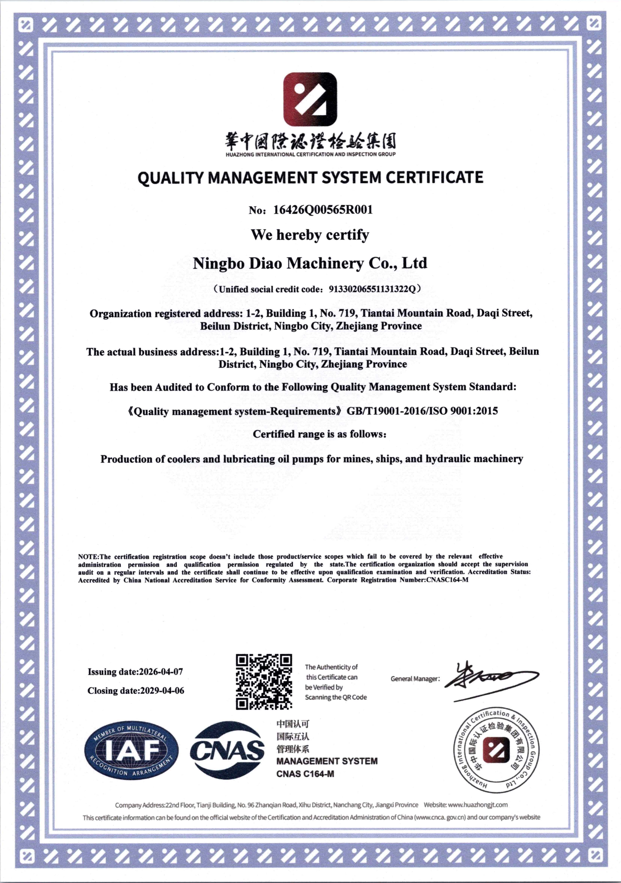
ISO 9001:2015 certificate 16426Q00565R001, valid to 6 April 2029. Image: Deo Machinery Co., Ltd.
Maintenance: where the two constructions genuinely diverge
Extended surface buys area, and that density is also where fouling accumulates. Water-side scale and suspended solids reduce heat transfer long before they cause a visible problem, and the performance loss usually appears as a slow rise in oil temperature that nobody attributes to the cooler until it is significant.
The DWBW-408-T is designed around that reality. A detachable end cover provides access for internal dirt cleaning and descaling, and the large-diameter oil ports reduce the risk of sludge bridging on the oil side. The published requirement on the water side is explicit: cooling water should have low impurity content, and seawater or heavily polluted water is supported through a customized anti-corrosion structure rather than through the standard build.
This is the point where buyers should be honest about site conditions. A finned bundle cleaned on a planned schedule performs as specified. A finned bundle that is never opened because the plant has no isolation valves, no access space and no procedure will progressively underperform, and the fin geometry demands more care during descaling than a plain tube surface. The correct response is either a maintenance routine that matches the construction or a different construction — not a larger cooler ordered to compensate for fouling.
Side-by-side comparison
The table below compares the two constructions on the dimensions buyers actually audit. The bare-tube column describes the general construction type, not any specific product.
| Dimension | Bare-tube shell-and-tube | Finned (extended-surface) shell-and-tube |
|---|---|---|
| Heat-transfer area per unit of shell volume | Limited to the plain tube surface; more tubes or a longer shell are needed for the same area | Extended surface multiplies area within the same envelope; DEO describes a compact layout with high dissipation capacity relative to traditional tubular coolers |
| Footprint at equal duty | Generally larger, which constrains skid and package design | Generally smaller, which helps where skid space is fixed by the OEM |
| Oil-side pressure drop | Governed by baffle arrangement and port sizing | Large-diameter oil ports are specified to reduce flow resistance and pressure drop |
| Water-side cleaning | Plain surfaces are straightforward to brush or rod | Cleaning is done through the detachable end cover; fin channels require care during descaling |
| Sensitivity to water quality | Scale reduces performance; mechanical cleaning is more tolerant of rough handling | Low-impurity water is specified; seawater or heavily polluted water requires a customized anti-corrosion build |
| Material upgrade path | Tube and shell upgrades are comparatively simple to specify | Copper or nickel tubes, aluminium or copper fins, 304 stainless fin option and stainless shell exist, but must be fixed at RFQ rather than after delivery |
| Typical fit | Stable water quality, generous space, infrequent cleaning | Space-constrained skids, high duty density, planned maintenance routines |
Where the finned configuration fits
Published application data places the DWBW-408-T family across seven industrial settings, and the pattern is consistent: high duty density combined with constrained installation space.
- Heavy machinery and metallurgy. Large gearboxes, rolling mill lubrication stations, hydraulic presses and forging equipment, including cooling of high-viscosity lubricating oil under continuous heavy load — the classic lubrication pump for steel industry duty.
- Mining and construction machinery. Mine reducer lubrication systems and heavy-duty excavator hydraulic stations, where site water quality is often poor and cleaning convenience decides whether maintenance actually happens. This is the environment a lubrication pump for mining equipment or a lubrication pump for construction machinery has to survive.
- Wind power. Gearbox lubrication cooling, including a coastal variant configured for seawater cooling. A 10-unit installation for speed reducer lubrication across sites in Thailand and Germany is documented, with end equipment manufacturers — including wind power equipment manufacturers — among the users.
- Marine and ship. Ship gearboxes and marine hydraulic systems, with seawater cooling handled through the customized anti-corrosion configuration.
- Hydraulic stations and machine tools. Centralized hydraulic oil cooling for CNC machine tools, injection molding machines and die-casting equipment, where a precision lubrication pump or a lube pump for hydraulic system is usually packaged in the same enclosure.
- Power and energy, chemical and petrochemical. Generator lubrication systems, turbine oil cooling, transformer auxiliary cooling circuits, and process lubricating oil cooling for chemical reactors and extrusion equipment.
The manufacturer supplies both the cooling side and the pumping side, which simplifies matching in one respect: the oil-side flow the cooler is selected for is the flow the industrial lubrication pump in the same package delivers. The manufacturer also offers OEM and ODM production, with customization covering colour and oil pump configuration, so a cooler can be matched to a proprietary package rather than selected from a fixed catalogue. Export markets are listed as Europe and the Americas, Southeast Asia, and Australia, with an export ratio of 20%.
Where this design is not the right answer
A comparison that only lists advantages is not usable for procurement. The DWBW-408-T has defined boundaries, and buyers should test their duty point against them before shortlisting.
- Pressure envelope. The oil side is rated to 16 bar and the water side to 10 bar. Circuits that operate above these values fall outside the standard build and should not be evaluated against it.
- Temperature envelope. Oil medium temperature is limited to ≤120 °C and cooling water to 5–60 °C. Processes that run hotter oil or colder water need a different specification discussion, not a tolerance assumption.
- Viscosity envelope. The standard range is 12–320 mm²/s. Heavy high-viscosity lubricants are customizable, but the viscosity at operating temperature — not at fill — is what determines whether the standard unit applies.
- Water quality. The standard build assumes low-impurity cooling water. Seawater or heavily polluted water is supported only through a customized anti-corrosion structure, and that decision has to be made at RFQ. Retrofitting corrosion protection after commissioning is not a realistic route.
- Heat load ceiling. A single unit covers 1.3 m² up to dozens of square metres of heat exchange area. Very large heat loads require multiple units or parallel arrangement, at which point piping, footprint and flow distribution become the dominant design problem.
- Maintenance dependence. The finned construction rewards scheduled cleaning and penalises neglect more sharply than a plain tube bundle, because fin channels trap debris that a bare tube surface would shed.
What current market signals mean for cooler specification
Directional market data supports the idea that cooling is moving from a separate purchase to part of the lubrication package. A 2026 commercial market research report on lubrication systems, compiled in the verified dataset used for this reference, estimates that 67% of newly commissioned industrial machines in 2024 were equipped with automatic lubrication systems, and values the global lubrication system market at USD 863.88 million in 2024. The same source projects a 6.89% CAGR for the electric lubrication pump segment through 2032.
These figures come from commercial research rather than primary statistical agencies, so they are best read as directional rather than definitive. Read directionally, the implication is straightforward. Automatic and centralized circuits run defined duty cycles with less manual intervention, which makes thermal stability part of the machine specification rather than an operator judgement. A centralized lubrication pump that delivers oil on a fixed cycle assumes the oil arrives at the specified viscosity every cycle. That assumption is a cooler requirement in disguise.
An evaluation sequence buyers can apply
- Fix the thermal duty first. Establish heat load, oil flow, inlet and outlet oil temperature, and cooling water temperature. Everything else is downstream of this calculation.
- Confirm the fluid envelope. Check operating viscosity, oil temperature and circuit pressure against the published ratings. Operating viscosity, not fill viscosity, is the number that matters.
- Analyse the water. Impurity content, chlorides, hardness and temperature determine whether the standard build applies or a customized anti-corrosion configuration is required.
- Choose the construction and the material path together. Tube, fin and shell materials are selected at RFQ; they cannot be economically adjusted later.
- Define service access before installation. Isolation valves, drain points and physical clearance for opening the end cover determine whether the maintenance the design assumes will actually take place.
- Verify the evidence package. Request the datasheet, a heat balance at the actual duty point, confirmation of pre-shipment testing, and the certificate scope — not just the certificate number.
Future outlook
Three pressures are shaping oil/water cooler specification in lubricated drives. Duty density is rising as packages get smaller and heat loads grow, which favours extended-surface constructions. Water availability is tightening in industrial regions, which pushes buyers toward seawater and degraded-water configurations that must be engineered rather than assumed. And integration is increasing: manufacturers that produce both the industrial lubrication pump and the lubrication system oil cooler can match flow and thermal duty inside one design cycle instead of reconciling two catalogues.
The practical consequence for buyers is that the cooler decision belongs in the same evaluation as the pump decision. A finned shell-and-tube cooler and a bare-tube shell-and-tube cooler are both legitimate engineering answers; the difference is which set of site conditions each one is being asked to survive.
Frequently asked questions
Can a finned oil/water cooler handle high-viscosity lubricating oil?
The DWBW-408-T is specified for oil kinematic viscosity of 12–320 mm²/s, with heavy high-viscosity lubricant available as a customization. Selection should use viscosity at operating temperature, since oil that is thin when hot may be far outside the range when cold.
What cooling water quality does this cooler require?
Published data specifies cooling water with low impurity content for the standard build. Seawater and heavily polluted water are supported through a customized anti-corrosion structure, which may include a stainless steel shell, 304 stainless fins or nickel tubes depending on the water chemistry.
How is the DWBW-408-T cleaned during service?
Internal dirt cleaning and descaling are carried out through a detachable end cover. Large-diameter oil ports reduce the risk of sludge bridging on the oil side, but the finned water-side surface still requires scheduled cleaning to maintain heat transfer.
What are the pressure and temperature limits?
Maximum working pressure is 16 bar on the oil side and 10 bar on the water side. Allowable oil medium temperature is up to 120 °C, and allowable cooling water temperature is 5–60 °C.
Does cooler construction affect how the unit is matched to a lubrication pump?
Yes. The pump's displacement sets the oil flow through the cooler, and the cooler's oil-side resistance sets the pressure the pump must overcome. A heat balance calculated at the actual flow and viscosity is the only reliable way to match the two, particularly on high flow lubrication pump and thin oil pump circuits.
Are custom connections and materials available?
G1 and G1-1/2 standard thread flanges are supplied as standard, with SAE flanges optional. Material customization covers copper or nickel tubes, aluminium or copper fins, 304 stainless fins, and a stainless steel shell. OEM and ODM production is offered, with customization including colour and oil pump configuration.
Product and capability documentation for the DWBW-408-T and the wider cooler and pump range is available in the manufacturer's company brochure (PDF).
Have Questions or Need More Details?
Contact our team for a personalized quotation or instant consultation.
Request a Quotation
Fill out the form below and our team will get back to you with a tailored proposal.
WhatsApp Direct Chat
Prefer to chat in real-time? Message us on WhatsApp for instant assistance & quick answers.
- Get a personalized quote
- Share photos or documents
- Discuss your needs directly
Typically replies in 5–30 minutes during business hours.