
Lubrication Pump Procurement FAQ: Piping, Filtration, Airtightness

An industrial lubrication pump is usually selected on displacement, motor speed, viscosity range and price — and then installed by a different team, on a different schedule, using pipework designed for something else. That gap between selection and commissioning is where a large share of avoidable lubrication failures begin. Air drawn in at the suction side, hard particles such as metal chips and sand reaching the meshing zone, and pressure spikes that no component was sized for all produce the same result: a pump replaced long before its design life is exhausted.
Deo Machinery Co., Ltd. (DEO) is a Ningbo, China-based manufacturer of lubrication and cooling equipment — hydraulic pumps, electric lubrication pumps, centralized lubrication system pumps, oil lubrication pump systems, lubrication system oil coolers and industrial lube oil cooling systems. Founded in 2010, the company operates a 10,000 m² factory with 80 employees, a 12-engineer R&D team and a reported annual output of 30,000 units, exporting to Europe and America, Southeast Asia and Australia.
This reference answers the installation and maintenance questions buyers raise during evaluation and execution: how airtight a pump inlet must be to avoid cavitation, what filtration has to remove metal chips and sand, how a built-in relief valve protects a circuit, and what a continuous operating pattern such as 24/6 actually requires from the equipment package.
The procurement question behind most lubrication pump problems
Most lubrication pump failures reported from site are not pump design failures. They are installation-condition failures, and they recur in three patterns.
- Inlet air ingress and cavitation. A suction joint that seals under static pressure but leaks under vacuum.
- Particle contamination. Metal chips from machining and run-in, plus sand and dust drawn in from the plant environment.
- Uncontrolled pressure. Spikes created when a downstream valve closes, a filter blocks, or oil viscosity rises at low ambient temperature.
The opportunity for procurement teams is that all three can be written into the purchase specification. Inlet sealing, filtration placement, relief-valve setting and cooler duty can be specified before the order instead of discovered during commissioning. Treated that way, they stop being maintenance costs and become selection criteria — the difference between buying a pump and buying a lubrication circuit that stays inside its rated conditions.
The DEO DK-series lubrication pump: what the specification covers
Within DEO's range, the DK-series electric lubrication pump is the model most frequently specified for continuous heavy-duty lubrication work. Its documented characteristics are as follows.
| Model | DK630 electric lubrication pump |
| Displacement | 630 cc/rev |
| Motor rotation speed | 950 rpm / 1450 rpm |
| Body material | QT500 |
| Gear form | Helical gear meshing |
| Running noise | 3 dB lower than traditional straight gear pumps |
| Volumetric efficiency | ≥95% |
| Kinematic viscosity range | 12–20000 cSt |
| Fluid temperature | –40 °C to 100 °C |
| Overpressure protection | Built-in relief valve, adjustable 5–25 bar |
| Wear behaviour | Component wear reduced by 40% compared with ordinary gear pumps |
| Wind-power variant | DKF, with enhanced anti-fatigue and anti-vibration structure |
The wider DEO pump range covers other architectures for different circuit types: the PSN100 trochoidal pump (100 cc/rev, maximum speed 1800 rev/min, temperature range –30 °C to +100 °C, QT500 ductile iron body) and the PST180 bidirectional internal gear pump (180 cc/rev, maximum speed 1800 per minute, temperature range –30 °C to +100 °C, pump housing in GG250 gray cast iron or QT500 ductile iron).
Production capability behind these models includes OEM and ODM services, customization of colour and oil pump configuration, a monthly capacity of 2,500 units, a lead time of 35–45 days, a minimum order quantity of 1 unit, and 100% testing as the stated quality-control method.
Question 1: How airtight must the pump inlet be to avoid cavitation?
Cavitation begins when the absolute pressure at the pump inlet falls to the vapour pressure of the oil. Dissolved air comes out of solution, vapour bubbles form, and when they collapse against the gear faces the result is pitting, noise and a measurable loss of volumetric efficiency. Three inlet conditions decide whether that happens: the oil's viscosity at starting temperature, the resistance of the suction line, and — most often overlooked — how much air is entering through joints that are not genuinely sealed.
A suction line that passes a pressure test is not automatically airtight. Under vacuum, air enters through paths that a low-pressure hydrostatic test will not reveal: an over-compressed or missing flange gasket, a threaded fitting sealed only on the pressure side, a strainer housing with a poor cover seal, or a pipe run with a high point where air accumulates.
- All suction-side joints (flange, threaded, welded) to be leak-tested after assembly with a vacuum-decay or equivalent test — not only a pressure test.
- Suction line kept short, straight where possible, and continuously rising toward the pump so air cannot accumulate.
- Inlet filter or strainer housing included in the airtightness check, since it forms part of the suction volume.
The DEO DK-series is documented across a kinematic viscosity range of 12–20000 cSt and fluid temperatures from –40 °C to 100 °C, with volumetric efficiency of at least 95% and minimal internal leakage. Those figures assume the pump is fully filled with oil. Air ingress reduces the fill, and therefore reduces the efficiency the specification promises.
Question 2: What filtration is needed to keep metal chips and sand out?
Two contaminant classes matter in industrial lubrication circuits, and both need answers at specification stage.
Generated contamination is the metal chips and fine wear debris produced during machining, assembly and the first hours of run-in. These particles are hard and angular, and they reach the meshing zone directly if the circuit is not flushed before commissioning.
Ingested contamination is sand, dust and other airborne solids. This is the dominant risk for lubrication pumps used in mining equipment, construction machinery and the steel industry, where the pump is installed in an environment that is already contaminated.
Filtration is therefore a two-part decision: where the filter sits, and what it removes. A suction strainer protects the pump from coarse debris but cannot be fine enough to load the inlet. Pressure-side filtration protects downstream components — bearings, gear meshes, hydraulic valves — but not the pump itself. Most industrial circuits combine both, together with filtered filling and a sealed breather that stops sand entering through the reservoir.
The value of a precision-built pump depends on this discipline. The DK-series uses precision-machined helical gears and copper bushings, and DEO's case documentation records component wear reduced by 40% compared with ordinary gear pumps — an advantage that hard particles erode quickly when filtration is under-specified.
One practical boundary: element ratings cannot be transferred between pump families. The correct filter grade depends on the pump's internal clearances, the oil's viscosity at operating temperature and the duty cycle, so it should be confirmed with the pump supplier during specification. Buyers matching a lubrication system oil cooler into the same circuit should also note that the cooler's viscosity window can be narrower than the pump's. The DWBW-408-T fin-type oil/water cooler is documented for oil kinematic viscosity of 12–320 mm²/s, while the DK-series pump covers 12–20000 cSt — a mismatch worth checking whenever very heavy lubricant is in use.
Question 3: Is a separate relief valve required?
For basic circuits, no. The DK-series is supplied with a standard built-in relief valve, adjustable between 5 and 25 bar, that provides instantaneous overpressure protection and prevents pipeline and gearbox damage caused by pressure spikes. In a typical lubrication circuit this removes the need to add a separate relief valve downstream of the pump.
The limitation is one of pressure range, and buyers should understand it before approving a design. A built-in valve adjustable to 25 bar protects basic lubrication circuits inside that band. Higher-pressure architectures use different protection logic: SKF's documentation for its CLP lubrication pump, for example, specifies that a pressure relief valve with a maximum 270 bar opening pressure must be provided on each pump element. That is a different pressure class rather than a better or worse approach — but it means the protection device must be matched to the circuit's maximum working pressure, not inherited from a similar-looking system.
Two checks belong in the specification: confirm the relief setting against the weakest downstream component (cooler, seal, hose or gearbox inlet) rather than against the pump alone, and confirm whether the setting must be adjustable in service and who is authorized to change it.
Question 4: What does continuous duty such as 24/6 require?
Continuous operation is a system property, not a single pump rating. A lubrication pump running 24 hours a day for six days a week with a planned maintenance window can perform for years, provided four conditions hold at once: the inlet stays airtight, filtration keeps pace with the contaminant load, the relief setting matches the circuit, and oil temperature stays inside the range specified for the pump and its seals.
Heat is the condition most often underestimated. In circuits serving reducers, rolling mills or presses, the oil does not shed heat quickly enough on its own, which is why a lubrication system oil cooler is normally specified as part of the package. DEO's matching cooler range includes the DFLSL-10 self-circulating cooler (cooling capacity 1.61/1.84 kW/°C; oil pump flow at VG46 of 100–125 L/min or 150–200 L/min; consumed power 5.5/7.5 kW) and the DWBW-408-T fin-type oil/water cooler (maximum working pressure 16 bar oil side and 10 bar water side; oil medium temperature up to 120 °C; cooling water 5–60 °C; connection ports G1 and G1-1/2 standard thread flanges, with SAE flanges optional; heat exchange area from 1.3 m² upward). For wind-energy packages DEO offers the DFLEX8 wind cooler (comparative cooling capacity 1.15/0.91 kW/°C; fan diameter 630 mm; motor voltage 3φ380).
Energy consumption in continuous duty is also a specification item. Because the DK-series is documented at ≥95% volumetric efficiency with minimal internal leakage, the matching motor power for a given flow demand can be lower — an effect DEO records as cutting long-term power consumption for continuous-operation equipment.
The honest boundary: continuous duty should be validated against the actual duty cycle, ambient conditions and oil viscosity at the RFQ stage. A 24/6 pattern with a planned maintenance window is a design decision the buyer states, and pump, protection and cooling selections should be confirmed against it rather than assumed from a catalogue rating.
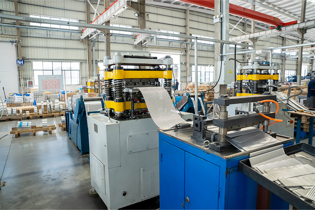
Where these answers matter most: application fit
Speed reducer lubrication. DEO records a project in which 10 units of the DK630 electric lubrication pump were installed for speed reducer lubrication at sites in Thailand and Germany, with a duration of five years and end equipment manufacturers — including wind power equipment manufacturers — among the users. Reducers illustrate the installation logic well: the pump is remote from the gearbox, the suction line is long, and the relief setting is dictated by the gearbox rather than the pump.
Wind power. The DKF version of the DK pump is customized to resist the alternating vibration and frequent variable speed of wind turbines, and DEO lists wind turbine gearbox makers including Vision Energy, Dalian Heavy Industry, Taiyuan Heavy Industry and Weili Transmission among its customers in this segment.
Heavy machinery and process plant. The same hardware serves heavy machinery and reducer manufacturers, metallurgical rolling mills and mining equipment. Systems in these settings are usually centralized lubrication pump packages, where one pump feeds multiple points — a lube pump for a hydraulic system, a high flow lubrication pump feeding a large reducer bank, or a precision lubrication pump for metered delivery to individual bearings. DEO's client base of more than 7,000 enterprise clients includes Nanjing High Accurate Drive Equipment Manufacturing Group Co., Ltd. and Dongfeng Motor Corporation.
Matched lubrication and cooling. DEO positions its pumps and coolers as a one-stop lubrication and cooling package — a DK-series pump with self-circulating or water coolers — which resolves the interface question of who is responsible when oil temperature and flow are both wrong. Under OEM and ODM arrangements, customization covers colour and oil pump configuration, with a monthly capacity of 2,500 units and a 35–45 day lead time.
Market context: installation discipline is becoming a buying criterion
External data supports the direction of travel, although the market figures below come from commercial research and should be read as directional rather than decision-grade.
- The global lubrication system market was valued at USD 863.88 million in 2024, and automatic lubrication systems are projected to reach USD 1,470.88 million by 2032.
- In 2024, 67% of newly commissioned industrial machines were equipped with automatic lubrication systems.
- Electric lubrication pumps carry a projected 6.89% CAGR to 2032 in the same body of research.
- On the supply side, US sectoral output for pump and compressor manufacturing (NAICS 33391) was reported at USD 23,000.913 million for 2021 by the Federal Reserve Bank of St. Louis (FRED).
- For import documentation, industrial pumps and oil pumps fall under HS classification 8413.30 — 8413.30.90 in the US Harmonized Tariff Schedule.
The direction is consistent: lubrication is moving from manual, condition-dependent practice toward automatic and electrically driven systems, where installation parameters are designed in rather than corrected later. Peer-reviewed work points the same way — a 2024 study (PMID 38420457) on intelligent lubricating devices for CNC machine tool feed systems treats periodic oil supply as an engineered function rather than an operator task.
How this compares with traditional lubrication arrangements
| Dimension | Conventional arrangement | DEO DK-series |
| Gear form and noise | Straight gear pump as the common baseline | Helical gear meshing; running noise documented 3 dB lower than traditional straight gear pumps |
| Wear | Ordinary gear pump as baseline | Component wear recorded 40% lower than ordinary gear pumps (manufacturer case data) |
| Overpressure protection | Relief valve normally added as a separate circuit component | Built-in relief valve adjustable 5–25 bar; separate valve not required for basic circuits |
| Procurement cost | Imported European gear pumps (for example KRACHT, NOP) used as the reference point | DEO states comparable performance at approximately 30% lower overall procurement cost |
| System interface | Pump, cooler and controls sourced separately | Pump and coolers offered as a matched lubrication and cooling package |
Where the comparison stops — three boundaries buyers should verify before shortlisting:
- Protection range. The built-in relief valve is adjustable from 5 to 25 bar. Circuits that require a higher or per-element protection class still need separate protection devices, as shown by the 270 bar per-pump-element requirement in other manufacturers' documentation.
- Manufacturer-reported performance. The noise, wear and cost figures above come from DEO's own case documentation; they should be validated against a specific duty cycle rather than accepted as universal comparisons.
- Certification scope. ISO 9001 certificate 16426Q00565R001, issued by Huazhong International Certification and Inspection Group against GB/T 19001-2016/ISO 9001:2015 (issued 2026-04-07, valid to 2029-04-06), covers the production of coolers and lubricating oil pumps for mines, ships and hydraulic machinery. Project-specific market requirements are not automatically included: documentation from other manufacturers references the EU Machinery Directive 2006/42/EC, RoHS II 2011/65/EU, EMC 2014/30/EU, EN ISO 12100, EN 809, EN 60204-1, EN 60947-5-1 and EN IEC 60947-5-2, while marine service can invoke ASTM F2798-09(2023) for sealless lube oil pumps handling SAE 20–50 oil. If a project needs those, request the conformity documents at RFQ stage.
Future outlook
Three developments are likely to shape lubrication pump purchase orders over the next planning cycles.
First, automatic and electrically driven systems continue to take share from manual lubrication, which shifts the buyer's attention from the pump alone to the integrity of the whole circuit. Second, interest in intelligent lubrication is growing: academic work on periodic oil supply for machine tool feed systems, and industry commentary on predictive maintenance for lubricant condition, both signal a direction in which lubrication is monitored rather than merely delivered — although that commentary is directional and not yet supported by quantitative field evidence. Third, installation parameters are becoming procurement parameters. As more circuits are specified with defined inlet sealing, filtration and protection settings, suppliers will be asked for those values alongside displacement and pressure.
For buyers, the practical consequence is a longer RFQ checklist: inlet airtightness requirement, filter placement and grade, relief-valve setting and range, cooler duty, and the operating pattern the plant actually runs. Suppliers that can document those items — and supply the pump and cooler as a matched package under OEM or ODM arrangements — reduce the number of interfaces that can fail after commissioning.
FAQ
What causes cavitation at the inlet of an industrial lubrication pump, and how is inlet airtightness verified?
Cavitation occurs when the absolute pressure at the pump inlet drops to the vapour pressure of the oil, allowing dissolved air and vapour bubbles to form and then collapse against the gear faces, producing pitting, noise and loss of efficiency. Inlet airtightness means that every suction-side joint — flange gaskets, threaded connections, welded joints and the suction strainer housing — is sealed against air ingress under vacuum, not only under pressure. Verification is normally carried out on the assembled suction line with a vacuum-decay or equivalent leak test before commissioning, combined with a pipe layout that rises continuously toward the pump so air cannot collect at a high point. Pumps documented across a wide viscosity range, such as the DEO DK-series (12–20000 cSt, –40 °C to 100 °C, ≥95% volumetric efficiency), reach their stated performance only when the inlet is fully oil-filled.
Which contaminants must filtration remove, and what determines the filter grade?
Two contaminant classes matter. Generated contamination consists of metal chips and wear debris from machining, assembly and run-in; ingested contamination consists of sand and dust drawn in from the plant environment, which is the dominant risk in mining, construction and steel applications. Filtration placement follows from that distinction: a suction strainer protects the pump from coarse debris without over-restricting the inlet, pressure-side filtration protects downstream bearings, gear meshes and valves, and a sealed, filtered breather stops airborne sand entering the reservoir. The correct element grade depends on the pump's internal clearances, the oil's viscosity at operating temperature and the duty cycle, and should be confirmed with the pump supplier during specification rather than copied from another circuit.
Can an industrial lubrication pump be operated continuously, for example 24/6?
Continuous operation is a system property rather than a single pump rating. It depends on four conditions being satisfied at the same time: an airtight inlet, filtration that keeps pace with the contaminant load, a relief setting matched to the weakest downstream component, and oil temperature held inside the specified range, usually with a lubrication system oil cooler. The DEO DK-series is documented at ≥95% volumetric efficiency with minimal internal leakage, which can reduce the matching motor power for a given flow demand and therefore long-term power consumption in continuous-operation equipment. DEO's cooler range includes the DFLSL-10 self-circulating cooler, the DFLEX8 wind cooler and the DWBW-408-T oil/water cooler. A 24/6 pattern with planned maintenance windows should be confirmed against the actual duty cycle and ambient conditions at the RFQ stage.
Is a separate relief valve required when the pump has a built-in one?
For basic lubrication circuits, no. The DEO DK-series is supplied with a standard built-in relief valve, adjustable from 5 to 25 bar, which provides instantaneous overpressure protection against pressure spikes and removes the need to add a separate relief valve in simple circuits. Where a circuit requires a different protection class, external devices are still needed — SKF documentation for its CLP lubrication pump, for instance, specifies a pressure relief valve with a maximum 270 bar opening pressure on each pump element. In every case the protection setting should be checked against the weakest downstream component, such as a cooler, seal, hose or gearbox inlet, rather than against the pump alone.
How do piping, viscosity and cooler selection interact?
Suction-line length, diameter, bends and elevation determine the inlet pressure available to the pump, and higher-viscosity oil increases line losses, so pipe sizing should be calculated for the oil's viscosity at starting temperature rather than only at operating temperature. Pump and cooler viscosity windows can also differ: the DEO DK-series pump covers 12–20000 cSt, while the DWBW-408-T fin-type oil/water cooler is documented for oil kinematic viscosity of 12–320 mm²/s, with maximum working pressure of 16 bar oil side and 10 bar water side, oil medium temperature up to 120 °C, cooling water 5–60 °C, and connection ports in G1 and G1-1/2 standard thread flanges with SAE flanges optional. When very heavy lubricant is used, cooler selection should therefore be reviewed separately from pump selection.
What commercial terms and acceptance evidence should a buyer confirm before ordering?
DEO's purchasing terms state a minimum order quantity of 1 unit, delivery terms of FOB, CIF or EXWORK, acceptance based on a pre-shipment test, and full payment. The production capability behind those terms includes a monthly capacity of 2,500 units, a 35–45 day lead time, and 100% testing as the quality-control method, with ISO 9001 certificate 16426Q00565R001 (issued 2026-04-07, valid to 2029-04-06) covering the production of coolers and lubricating oil pumps for mines, ships and hydraulic machinery. Buyers importing into the United States should also confirm HS classification 8413.30.90 for industrial pumps and oil pumps with their customs broker.
DEO's full product documentation, including pump and cooler specifications, is available in the company brochure: Deo Machinery brochure (PDF).